Service Manuals, User Guides, Schematic Diagrams or docs for : Mitac mitac w130
<< Back | HomeMost service manuals and schematics are PDF files, so You will need Adobre Acrobat Reader to view : Acrobat Download Some of the files are DjVu format. Readers and resources available here : DjVu Resources
For the compressed files, most common are zip and rar. Please, extract files with Your favorite compression software ( WinZip, WinRAR ... ) before viewing. If a document has multiple parts, You should download all, before extracting.
Good luck. Repair on Your own risk. Make sure You know what You are doing.
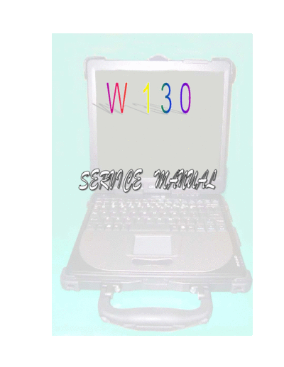
Image preview - the first page of the document

>> Download mitac w130 documenatation <<
Text preview - extract from the document
1 General system Description ........................................................................................5
    1.1 System Overview .............................................................................................5
       1.2 System Hardware Parts ....................................................................................7
       1.3 Major Component Introduction .......................................................................9
            1.3.1 CPU Module .........................................................................................9
            1.3.2 System frequency ICS950810...............................................................9
              1.3.3 Intel 855-GM GMCH IGUI 3D Graphic DDR/SDR Chipset.............10
              1.3.4 Memory System.................................................................................. 11
              1.3.5 Display ................................................................................................ 11
              1.3.6 HUB Interface for ICH4 .....................................................................14
              1.3.7 I/O Controller Hub: INTEL 82801DBM ............................................14
              1.3.9 Keyboard controller Hitachi H8/3437 ................................................17
              1.3.10 Fax/Modem module ..........................................................................18
              1.3.11 FAST ETHERNET CONTROLLER integrated ICH-4M ................18
         1.3.12 PCMCIA controller_ ENE CB1410 + ENE CP2211 ........................19
         1.3.13 AC"97 Code ALC202 .......................................................................19
         1.3.14 Thermal sensor_ ADM1021A...........................................................20
2 Motherboard Function Description...........................................................................21
       2.1 Hot Key Function...........................................................................................21
       2.2 Power on/off/suspend/resume button.............................................................21
       2.3 Cover Switch..................................................................................................22
       2.4 LED Indicators...............................................................................................22
     2.5 Battery status..................................................................................................23
     2.6 CMOS Battery ...............................................................................................23
     2.7 I/O Port...........................................................................................................23
3 Peripheral ..................................................................................................................26
       3.1 LCD PANEL ..................................................................................................26
       3.2 HDD...............................................................................................................26
       3.3 Keyboard........................................................................................................26
       3.4 Track Pad Synaptic ........................................................................................26
    3.5 Memory..........................................................................................................27
    3.6 Modem MDC .................................................................................................27
4 Power Management ..................................................................................................28
    4.1 System Management Mode............................................................................28
    4.2 Battery Life ....................................................................................................29
    4.3 Other power management functions ..............................................................29
5 Connector and Switch Definition..............................................................................30


                                                               2
6 System View .............................................................................................................38
    6-1 Front View .....................................................................................................38
    6-2 Bottom View..................................................................................................38
       6-3 Left-Side View...............................................................................................39
       6-4 Right-Side View ............................................................................................39
       6-5 Rear View ......................................................................................................40
       6-6 Top-open View...............................................................................................40
       6-7 Docking Module Front View .........................................................................41
       6-8 Docking Module Left-Side View...................................................................41
       6-9 Docking Module Right-Side View ................................................................42
       6-10 Docking Module Rear View ........................................................................42
7 System Disassembly .................................................................................................43
    7-1 Battery Pack...................................................................................................43
    7-2 Bottom Housing.............................................................................................44
    7-3 Modem Board ................................................................................................45
       7-4 Memory .........................................................................................................46
       7-5 HDD Module .................................................................................................47
       7-6 Keyboard .......................................................................................................48
       7-7 LCD Panel .....................................................................................................50
    7-8 System Board.................................................................................................51
    7-9 Touch Pad ......................................................................................................53
    7-10 Docking Mother Board................................................................................54
8 Location of Connectors / Major Components...........................................................56
       8-1 Mother Board
◦ Jabse Service Manual Search 2024 ◦ Jabse Pravopis ◦ onTap.bg ◦ Other service manual resources online : Fixya ◦ eServiceinfo