Service Manuals, User Guides, Schematic Diagrams or docs for : AIWA Минисистемы Минисистема Aiwa XR-EM20 XR-EM20
<< Back | HomeMost service manuals and schematics are PDF files, so You will need Adobre Acrobat Reader to view : Acrobat Download Some of the files are DjVu format. Readers and resources available here : DjVu Resources
For the compressed files, most common are zip and rar. Please, extract files with Your favorite compression software ( WinZip, WinRAR ... ) before viewing. If a document has multiple parts, You should download all, before extracting.
Good luck. Repair on Your own risk. Make sure You know what You are doing.
Image preview - the first page of the document
>> Download XR-EM20 documenatation <<
Text preview - extract from the document
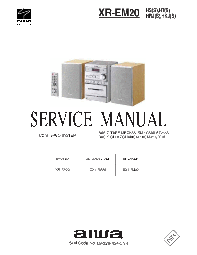
                                               HS(S),HT(S)
                         XR-EM20               HRJ(S),HKJ(S)


SERVICE MANUAL
CD STEREO SYSTEM
                         BASIC TAPE MECHANISM : CMAL5Z213A
                         BASIC CD MECHANISM : KSM-213RDM


       SYSTEM      CD-CASSEIVER     SPEAKER


      XR-EM20        CX-LEM20       SX-LEM20


                                                                 A
                                                             D AT
            S/M Code No. 09-029-454-3N4
TABLE OF CONTENTS - 1/1

SPECIFICATIONS ............................................................................................................................................................... 3
PROTECTION OF EYES FROM LASER BEAM DURING SERVICING ...................................................................... 4
ACCESSORIES PARTS LIST ............................................................................................................................................ 5
ELECTRICAL PARTS LIST ....................................................................................................................................... 6 ~ 16
CHIP RESISTOR PART CODE ....................................................................................................................................... 17
TRANSISTOR ILLUSTRATION ........................................................................................................................................ 18
SCHEMATIC DIAGRAM - 1/5 (MAIN) ............................................................................................................................... 19
WIRING - 1/7 (MAIN) <1 / 2> ............................................................................................................................................. 20
WIRING - 2/7 (MAIN) <2 / 2> ............................................................................................................................................. 21
SCHEMATIC DIAGRAM - 2/5 (FRONT / DECK) .............................................................................................................. 22
SCHEMATIC DIAGRAM - 3/5 (CD / DRIVE) .................................................................................................................... 23
WIRING - 3/7 (FRONT / CD) <1 / 2> ................................................................................................................................. 24
WIRING - 4/7 (FRONT / CD) <2 / 2> ................................................................................................................................. 25
SCHEMATIC DIAGRAM - 4/5 (PT) ................................................................................................................................... 26
WIRING - 5/7 (PT) .............................................................................................................................................................. 27
SCHEMATIC DIAGRAM - 5/5 (TUNER) ........................................................................................................................... 28
WIRING - 6/7 (TUNER) ...................................................................................................................................................... 29
WIRING - 7/7 (DECK) ........................................................................................................................................................ 30
IC BLOCK DIAGRAM ....................................................................................................................................................... 31
IC DESCRIPTION .................................................................................................................................................... 32 ~ 37
FL (HNA
◦ Jabse Service Manual Search 2026 ◦ Jabse Pravopis ◦ onTap.bg ◦ Other service manual resources online : Fixya ◦ eServiceinfo