Service Manuals, User Guides, Schematic Diagrams or docs for : AIWA Audio AM-C75 hfe_aiwa_am-c80_f80_c75_f75_f72_service_bulletin_nov_2000
<< Back | HomeMost service manuals and schematics are PDF files, so You will need Adobre Acrobat Reader to view : Acrobat Download Some of the files are DjVu format. Readers and resources available here : DjVu Resources
For the compressed files, most common are zip and rar. Please, extract files with Your favorite compression software ( WinZip, WinRAR ... ) before viewing. If a document has multiple parts, You should download all, before extracting.
Good luck. Repair on Your own risk. Make sure You know what You are doing.
Image preview - the first page of the document

>> Download hfe_aiwa_am-c80_f80_c75_f75_f72_service_bulletin_nov_2000 documenatation <<
Text preview - extract from the document
                                                                                                    1/1


                             Service Technical Information
  MODEL NO.
              AM -C80 / F80 / C75 / F75 / F72


  SUBJECT
              No power                                                   REF.No. :G - A0 - 084 - E0

                                                                         DATE      :01. NOV. 2000


   Check for the symptoms on the models concerned, and take the following countermeasures.


   Power is not turned on even if a rechargeable battery or an AC adapter is connected.
   And "OPEN" indication appears only when the lid of unit is opened.


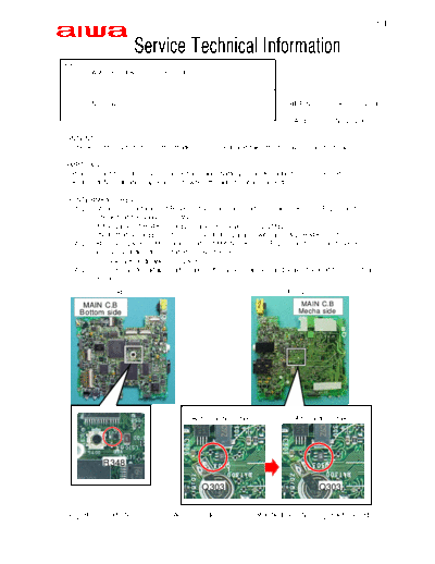
   Step 1: Measure resistance of R348 on the rear -panel side of main C.B. (See Fig -1) and
           check that the value is 2.2M .
           If the value of R348 is 100 , change the value into 2.2M .
           Note that a 100  resistor is connected in parallel with a 2.2M  R348 resistor.
   Step 2: Remove Q303 on Mechanism side of MAIN C.B. (See Fig - 2), and re -mount Q303
           in reversed direction (rotated in 180 degrees).
          Check "VK" indication on Q303.
   Step 3: Connect an AC adapter after taking the actions above, and leave the unit for more than
           8 hours.
                    Fig -1                                               Fig -2

        MAIN C.B                                                            MAIN C.B
       Bottom side                                                          Mecha side


                                           Before actions taken            After actions taken


                 R348

                                                Q303                              Q303


  G     R        Code No.             Access Code             Modified Ser. No.       Parts Schedule
   -    -            -                      -                        -                       -
◦ Jabse Service Manual Search 2024 ◦ Jabse Pravopis ◦ onTap.bg ◦ Other service manual resources online : Fixya ◦ eServiceinfo