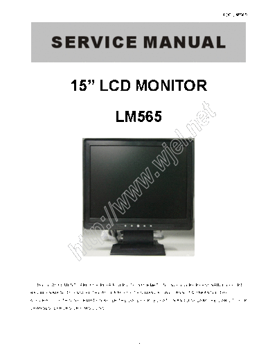
Service Manuals, User Guides, Schematic Diagrams or docs for : AOC Monitor LM565
<< Back | HomeMost service manuals and schematics are PDF files, so You will need Adobre Acrobat Reader to view : Acrobat Download Some of the files are DjVu format. Readers and resources available here : DjVu Resources
For the compressed files, most common are zip and rar. Please, extract files with Your favorite compression software ( WinZip, WinRAR ... ) before viewing. If a document has multiple parts, You should download all, before extracting.
Good luck. Repair on Your own risk. Make sure You know what You are doing.
Image preview - the first page of the document

>> Download LM565 documenatation <<
Text preview - extract from the document
                                                                              AOC LM565


        SERVICE MANUAL

                15" LCD MONITOR

                                  LM565


                                                                t
                                                         ne
                                                  el.
                                       wj
                                     w.
                           ww
                     ://
               tp
         ht


  THESE DOCUMENTS ARE FOR REPAIR SERVICE INFORMATION ONLY. EVERY REASONABLE EFFORT
HAS BEEN MADE TO ENSURE THE ACCURACY OF THIS MANUAL; WE CANNOT GUARANTEE THE
ACCURACY OF THIS INFORMATION AFTER THE DATE OF PUBLICATION AND DISCLAIMS RE LIABILITY FOR
CHANGES, ERRORS OR OMISSIONS.


                                            1
                                                                                                                              AOC LM565
                                                          Table of Content
Revision List.........................................................................................................................   3
1. Monitor Specifications........................................................................................................        4
2. LCD Monitor Description.....................................................................................................          5
3. Operating Instructions........................................................................................................        6
  3.1 General Instructions.........................................................................................................      6
  3.2 Front Panel Control..........................................................................................................      6
  3.3 Adjusting the Picture........................................................................................................      7
4. Input/Output Specification...................................................................................................         9
  4.1 Input Signal Connector.....................................................................................................        9
  4.2 Power Supply Requirements.............................................................................................             9
  4.3 Factory Preset Display Modes............................................................................................           10
  4.4 Panel Specification..........................................................................................................      11


                                                                                                       t
     4.4.1 Panel Feature...........................................................................................................      11


                                                                                           ne
     4.4.2 Display Characteristics................................................................................................       11
     4.4.3 Optical Characteristics................................................................................................       12
     4.4.4 Electrical Characteristics.............................................................................................       13


                                                                                el.
5. Block Diagram...................................................................................................................      14
  5.1 Monitor Explored View......................................................................................................        14
                                                            wj
  5.2 Software Flow Chart.........................................................................................................       15
  5.3 Electrical Block Diagram...................................................................................................        17
     5.3.1 Main Board..............................................................................................................      17
                                                          w.
     5.3.2 Inverter/Power Board.................................................................................................         18
6. Schematic.........................................................................................................................    19
                                          ww


  6.1 Main Board....................................................................................................................     19
  6.2 Power Board..................................................................................................................      25
  6.3 Audio Board...................................................................................................................     27
                               ://


7. PCB Layout.......................................................................................................................     28
  7.1 Main Board....................................................................................................................     28
  7.2 Power Board..................................................................................................................      29
                      tp


  7.3 Audio Board...................................................................................................................     30
  7.4 Keypad Board................................................................................................................       30
            ht


8. Maintainability...................................................................................................................    31
  8.1 Equipments and Tools Requirement....................................................................................               31
  8.2 Trouble Shooting.............................................................................................................      32
     8.2.1 Main Board...............................................................................................................     32
     8.2.2 Power /Inverter/Board................................................................................................         35
     8.2.3 Keypad Board...........................................................................................................       37
9. White-Balance, Luminance adjustment.................................................................................                  38
10. EDID Content...................................................................................................................      39
11. BOM List ........................................................................................................................    40
12. Different Parts List............................................................................................................     51


                                                                      2
                                                                        AOC LM565

                                      Revision List
Version      Date                    Revision History      TPV Model Name
 A00      Jan-12-06                   Initial Release      T560KV4DB4AOA
                        Add T560KH4DB4AOAPE
 A01      Jul-18-2006                                     T560KH4DB4AOAPE
                        in Item 12


                                                          t
                                                         ne
                                                        el.
                                        wj
                                      w.
                         ww
                ://
          tp
   ht


                                                3
                                                                                       AOC LM565
1. Monitor Specifications
               Items                                      Description

                         Driving system                    TFT Color LCD

                         Type                              SVA150XG04TB

                         Size                              38cm (15.0")
   LCD Panel
                         Pixel pitch                       0.297mm (H) x 0.297mm (V)

                         Viewable angle                    120(H) 100(V)

                         Response time                     16 ms

                         Sync. Type                        H/V TTL


                                                                           t
                                                                   ne
                         Input Signal                      15Pin Analog
   Input
                         H-Frequency                       30kHz
◦ Jabse Service Manual Search 2024 ◦ Jabse Pravopis ◦ onTap.bg ◦ Other service manual resources online : Fixya ◦ eServiceinfo