Service Manuals, User Guides, Schematic Diagrams or docs for : Agilent journals 1951-03
<< Back | HomeMost service manuals and schematics are PDF files, so You will need Adobre Acrobat Reader to view : Acrobat Download Some of the files are DjVu format. Readers and resources available here : DjVu Resources
For the compressed files, most common are zip and rar. Please, extract files with Your favorite compression software ( WinZip, WinRAR ... ) before viewing. If a document has multiple parts, You should download all, before extracting.
Good luck. Repair on Your own risk. Make sure You know what You are doing.
Image preview - the first page of the document
>> Download 1951-03 documenatation <<
Text preview - extract from the document
                                                                       HEWLETT-PACKARD


                                                  JOURNAL
                                                  T E C H N I C A L    I N F O R M A T I O N   F R O M   T H E   - h p -   L A B O R A T O R I E S
                                                                                                                                                           VOL. 2. No. 7-8


'UBLISHED BY THE HEWLETT-PACKARD COMPANY, 395 PAGE MILL ROAD, PALO ALTO, CALIFORNIA MARCH-APRIL, 1951


                                               Power Measurements from
                                                10 to 12,400 Megacycles
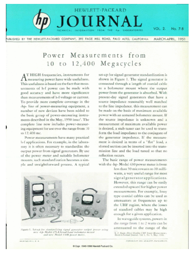
       A F HIGH frequencies, instruments for                                                   set-up for signal generator standardization is
            measuring power have wide usefulness.                                              shown in Figure 1 . The signal generator is
       This usefulness is based on the fact that meas                                          connected through a length of coaxial cable
       urements of h-f power can be made with                                                  to a bolometer mount where the output
       good accuracy and have more significance                                                power from the generator is absorbed. With
       than measurements of h-f voltage or current.                                            present-day signal generators that have a
       To provide more complete coverage in the                                                source impedance reasonably well matched
       -hp- line of power-measuring equipment, a                                               to the line impedance, this measurement can
       number of new devices have been added to                                                be made on the basis of maximum available
       the basic group of power-measuring instru                                               power with an untuned bolometer mount. If
       ments described in the May, 1950 issue1. The                                            the source impedance is unknown and a
       complete line now includes power-measur                                                 measurement of maximum available power
       ing equipment for use over the range from 10                                            is desired, a stub tuner can be used to trans
       to 12,400 me.                                                                           form the load impedance to the conjugate of
          Power measurements have many practical                                               the generator impedance. If the measure
       h-f applications. For example, in the labora                                            ment is desired in terms of a "flat" load, a
       tory it is often necessary to standardize the                                           slotted section can be inserted into the trans
       output power from signal generators. By use                                             mission line and the load tuned so that no
       of the power meter and suitable bolometer                                               reflection occurs.
       mounts, such standardization becomes a sim                                                 The basic range of power measurements
       ple and straightforward process. A typical                                              with the -hp- Model 430 power meter is from
                                                                                                          less than 50 microwatts to 10 milli
                                                                                                          watts, a very useful range for most
                                                                                                          s i g n al g en era t o r ap p l i cat i o n s .
                                                                                                          However, this range can be easily
                                                                                                          extended upward for higher power
                                                                                                          measurements. For example, lossy
                                                                                                          type coaxial cables can be used as
                                                                                                          attenuators at frequencies up to
                                                                                                          the UHF region, where the losses
                                                                                                          of standard cables may be high
                                                                                                          enough for a given application.
                                                                                                              In waveguide systems, powers in
                                                                                                          the range from 1 to 2 watts can be
        Figure using Set-up for standardizing signal generator output                      poirer using
                                                                                                          attenuated to the range of the
                  new -hp- ¿Model 476A broad-hand holometer nmnnt                                                'B. P. Hand, Direct Reading L'HF Power Measurements,
                           and neu Model -t HIB poner meter.                                                       Hewlett-Packard Journal. Vol. 1. o. <(. May, 1950.

       P R I N T E D   I N   U .   S .   A .                                                                                     COPYRIGHT 195! H E WLETT - PAC K ARO CO.
◦ Jabse Service Manual Search 2026 ◦ Jabse Pravopis ◦ onTap.bg ◦ Other service manual resources online : Fixya ◦ eServiceinfo