Service Manuals, User Guides, Schematic Diagrams or docs for : Agilent journals 1951-09
<< Back | HomeMost service manuals and schematics are PDF files, so You will need Adobre Acrobat Reader to view : Acrobat Download Some of the files are DjVu format. Readers and resources available here : DjVu Resources
For the compressed files, most common are zip and rar. Please, extract files with Your favorite compression software ( WinZip, WinRAR ... ) before viewing. If a document has multiple parts, You should download all, before extracting.
Good luck. Repair on Your own risk. Make sure You know what You are doing.
Image preview - the first page of the document
>> Download 1951-09 documenatation <<
Text preview - extract from the document
                                          £^^ HEWLETT-PACKARD


                               (Kg) JOURNAL
                                          f *   T E C H N I C A L   I N F O R M A T I O N   F R O M   T H E   - h p -   L A B O R A T O R I E S
                                                                                                                                                                                   VOL. 3 No. 1


'UBLISHED BY THE HEWLETT-PACKARD COMPANY, 395 PAGE MILL ROAD, PALO ALTO, CALIFORNIA SEPTEMBER, 1951


                      Good Practice in Slotted Line Measurements

         A REVIEW of the literature will disclose                                                  characteristic of the various devices used in
       A\. that much has been written on the sub                                                   slotted line work.
       ject of proper techniques for making meas                                                      A generalized set-up for measurements
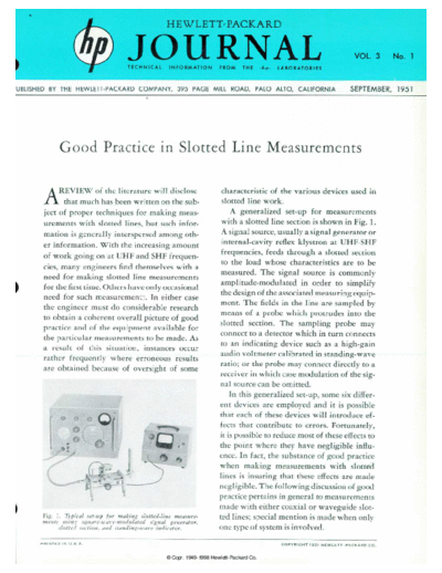
       urements with slotted lines, but such infor                                                 with a slotted line section is shown in Fig. 1.
       mation is generally interspersed among oth                                                  A signal source, usually a signal generator or
       er information. With the increasing amount                                                  internal-cavity reflex klystron at UHF-SHF
       of work going on at UHF and SHF frequen                                                     frequencies, feeds through a slotted section
                                                                                                   to the load whose characteristics are to be
       cies, many engineers find themselves with a
                                                                                                   measured. The signal source is commonly
       need for making slotted line measurements
       for the first time. Others have only occasional                                             amplitude-modulated in order to simplify
       need for such measurement. In either case                                                   the design of the associated measuring equip
                                                                                                   ment. The fields in the line are sampled by
       the engineer must do considerable research
                                                                                                   means of a probe which protrudes into the
       to obtain a coherent overall picture of good
                                                                                                  slotted section. The sampling probe may
       practice and of the equipment available for
                                                                                                  connect to a detector which in turn connects
       the particular measurements to be made. As
                                                                                                   to an indicating device such as a high-gain
       a result of this situation, instances occur
                                                                                                  audio voltmeter calibrated in standing- wave
       rather frequently where erroneous results
       are obtained because of oversight of some                                                  ratio; or the probe may connect directly to a
                                                                                                  receiver in which case modulation of the sig
                                                                                                  nal source can be omitted.
                                                                                                      In this generalized set-up, some six differ
                                                                                                  ent devices are employed and it is possible
                                                                                                  that each of these devices will introduce ef
                                                                                                  fects that contribute to errors. Fortunately,
                                                                                                  it is possible to reduce most of these effects to
                                                                                                  the point where they have negligible influ
                                                                                                  ence. In fact, the substance of good practice
                                                                                                  when making measurements with slotted
                                                                                                  lines is insuring that these effects are made
                                                                                                  negligible. The following discussion of good
                                                                                                  practice pertains in general to measurements
                                                                                                  made with either coaxial or waveguide slot
       Fig. 1. Typical set-up for making slotted-line measure                                     ted lines; special mention is made when only
       ments using sqitare-icave-modiilated signal generator,
             slotted section, and standing-wave indicator.                                        one type of system is involved.
      P R I N T E D   I N   U . S . A .                                                                                        C O P Y R I G H T   1 9 5 1   H E W L E T T - P A C K A R D   C O .
◦ Jabse Service Manual Search 2026 ◦ Jabse Pravopis ◦ onTap.bg ◦ Other service manual resources online : Fixya ◦ eServiceinfo