Service Manuals, User Guides, Schematic Diagrams or docs for : Agilent journals 1951-11
<< Back | HomeMost service manuals and schematics are PDF files, so You will need Adobre Acrobat Reader to view : Acrobat Download Some of the files are DjVu format. Readers and resources available here : DjVu Resources
For the compressed files, most common are zip and rar. Please, extract files with Your favorite compression software ( WinZip, WinRAR ... ) before viewing. If a document has multiple parts, You should download all, before extracting.
Good luck. Repair on Your own risk. Make sure You know what You are doing.
Image preview - the first page of the document
>> Download 1951-11 documenatation <<
Text preview - extract from the document
                                                                             HEWLETT'PAGKARD


m p   ' f   T E C H N I C A L
                                                          JOURNAL
                                                I N F O R M A T I O N         F R O M     T H E     - n p -       L A B O R A T O R I E S
                                                                                                                                                                                 VOL. 3 No. 3


| PUBLISHED BY THE HEWLETT-PACKARD COMPANY, 395 PAGE MILL ROAD, PALO ALTO, CALIFORNIA NOVEMBER, 1951


                                            Recent Developments in -hp-
                                         Waveguide Type Measuring Equipment
                     February, 1951, issue of the Journal                                          loading are interdependent. To obtain high
              J_ announced the -hp- program for a com                                              probe output, then, the designer must con
             plete series of waveguide measuring equip                                             struct a probe having high efficiency; that is,
             ment to cover the frequency range from 2600                                           a probe having maximum output for a given
             to 18,000 megacycles. At that time the Model                                          loading effect on the line.
             810 interchangeable slotted sections, the                                                In tuned type probes the probe tuner in
             Model 442 and 444 probes, and the Model                                               creases the efficiency of the probe by adjust
             440 detector mount were described. The suc                                            ing the match between the probe antenna
             ceeding issue described the Model 485 de                                              and the detector element. From an opera
             tector mounts, the Model 370 fixed attenu                                             tional standpoint, however, a tuned probe is
             ators, and the Model 912 high-power ter                                               inconvenient to use. If the probe is a single
             minations.                                                                            adjustment type, the probe must be retuned
                Since those issues were published, a num                                           for each change of frequency. If the probe is
             ber of other items have been put into pro                                             a two-adjustment type, not only must the
             duction. In addition, considerable interest                                           probe be retuned when frequency is changed
             has been shown in the Model 444 untuned                                               but the tuning operation itself is often diffi
             probe and Model 806B coaxial slotted sec                                              cult. Consideration of these factors led to a
             tion, and pertinent application data regard                                           decision to design the Model 444A as an un
             ing these devices will be presented here.                                             tuned probe. To accomplish such a design, it
              UNTUNED PROBE                                                                        becomes necessary to make the probe as effi
                 A realistic measure of electrical quality                                         cient as possible.
              for an r-f probe designed for slotted line                                              Since no tuner was to be incorporated in
              work is the relation of probe rectified output                                       the probe, it was extremely important that
              to loading on the line caused by the probe.                                          residual reactances between the probe an
              However, since probe output is obtained at                                           tenna and the probe detector element be held
              the expense of extracting energy from the                                            at a minimum. This was achieved by locating
              line, the characteristics of probe output and                                        the detector element unusually close to the
                                                                                                   antenna and by using a type 1N26 silicon
                                                                                                   crystal whose construction was more suitable
                                                                                                   than other types for the purpose. As a result
                                                                                                   of this design, the rectified output of the
                                                                                                   Model 444A was high, relatively constant
                                                                                                   over wide r-f frequency ranges, and did not
                                                         -hp-MOOEL444/i                            exhibit the large peaks and troughs common
                                                   KILOMEGACYCLES                                  with conventional probes.
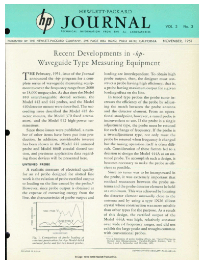
                              Fig. 1. Comparison of probe loading at                                 ï:For a description of probe loading effects, see "Good Practice in
                              constant penetration for -hp- Model 444A                                Slotted Line Measurements," Hewlett-Packard Journal, Vol. 3,
                              untuned probe and for tii'o tuned probes.                               Nos. 1 and 2, September and October, 1951.


            P R I N T E D   I N   U . S . A .                                                                                 C O P Y R I G H T   1 9 5 1   H E W L E T T - P A C K A R D   C O .
◦ Jabse Service Manual Search 2026 ◦ Jabse Pravopis ◦ onTap.bg ◦ Other service manual resources online : Fixya ◦ eServiceinfo