Service Manuals, User Guides, Schematic Diagrams or docs for : Agilent journals 1953-01
<< Back | HomeMost service manuals and schematics are PDF files, so You will need Adobre Acrobat Reader to view : Acrobat Download Some of the files are DjVu format. Readers and resources available here : DjVu Resources
For the compressed files, most common are zip and rar. Please, extract files with Your favorite compression software ( WinZip, WinRAR ... ) before viewing. If a document has multiple parts, You should download all, before extracting.
Good luck. Repair on Your own risk. Make sure You know what You are doing.
Image preview - the first page of the document
>> Download 1953-01 documenatation <<
Text preview - extract from the document
                                                      HEWLETT-PACKARD

                                            JOURNAL
                                            TECHNICAL INFORMATION FROM THE -h p- LABORATORIES
                                                                                                                                           VOL. 4 No. 5-6


PUBLISHED BY THE HEWLETT-PACKARD COMPANY, 395 PAGE MILL ROAD, PALO ALTO, CALIFORNIA JAN. -FEB., 1953


            More About the -hp- Precision Directional Couplers
        AV earlier issue1 described the design of                             incident on any device connected at the end
              the -hp- 10 and 20 db precision multi-                          of the guide. The other part of the power is
        hole directional couplers. These couplers are                         coupled into the auxiliary guide. It is a prop
        distinguished by a relatively constant coup                           erty of directional couplers that the power
        ling over a wave guide range of frequencies                           coupled into the auxiliary guide flows essen
        and by an unusually high directivity of more                          tially in only one direction. In the -hp- coup
        than 40 db, even for coupling values as tight                         ler, this power flow is in the same direction
        aslOdb.                                                               as the power in the primary guide.
           The multi-hole coupler design has now                                 In the ideal condition all of the power
        been extended to a 3 db coupler, that is, a                           coupled to the auxiliary guide should flow in
        coupler in which half the power entering the                          the same direction. Practically, however, a
        main guide is coupled into the auxiliary                              portion of the auxiliary guide power flows
        guide. This coupler has the same constancy                            in the reverse direction. The ratio of auxil
        of coupling and high directivity as the 10 and                        iary guide power flowing in the desired di
        20 db values. In addition, specifications have                        rection to that flowing in the reversed direc
        been established for all couplers on the basis                        tion is termed the directivity of the coupler.
        of production experience.                                             In the past the use of directional couplers has
           The -hp- multi-hole couplers consist of                            been limited by lack of high directivity over
        two sections of wave guide mutually coupled                           a full wave guide frequency range. It is this
        by two rows of coupling holes (Fig. 2).                               feature of high directivity over a broad range
        Power entering the input arm of the coupler                           that has received the attention of designers
        flows down the main guide and divides at the                          in recent years and it is in this feature that
        coupling mechanism. Part of the power con                             the -hp- multi-hole couplers are distinctive.
        tinues down the main guide where it will be                              To a first order effect, the lengths of the
                                                                                            rows of coupling holes shown in
                                                                                            Fig. 2 are chosen to obtain very-
                                                                                            high directivity for the coupling
                                                                                            mechanism itself. The voltage
                                                                                            coefficients of coupling of the in
                                                                                            dividual holes are separately
                                                                                            chosen to obtain the desired cou
                                                                                            pling value and at the same time
                                                                                            to obtain the desired type of re
                                                                                            verse radiation spectrum. The
                                                                                            reverse radiation is designed to
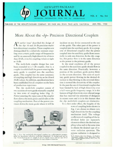
        Fig. 1. Tu'o -hp- multi-hole directional couplers in a reflectometer arrange
        ment for measuring reflection coefficient magnitude. In background are an          'E. F. Harriett and J. K. Hunton, "A Precision
        -hp- 7 -hp- A klystron pou'er supply to pouer signal source and an -hp- 41 5 A      Directional Coupler Using Multi-Hole Coup
                                                                                            ling," Hewlett-Packard Journal, Vol. 3, No. 7-8,
                      standing-wave indicator to read output of detector.                   March-April, 19
◦ Jabse Service Manual Search 2026 ◦ Jabse Pravopis ◦ onTap.bg ◦ Other service manual resources online : Fixya ◦ eServiceinfo