Service Manuals, User Guides, Schematic Diagrams or docs for : Agilent journals 1955-01
<< Back | HomeMost service manuals and schematics are PDF files, so You will need Adobre Acrobat Reader to view : Acrobat Download Some of the files are DjVu format. Readers and resources available here : DjVu Resources
For the compressed files, most common are zip and rar. Please, extract files with Your favorite compression software ( WinZip, WinRAR ... ) before viewing. If a document has multiple parts, You should download all, before extracting.
Good luck. Repair on Your own risk. Make sure You know what You are doing.
Image preview - the first page of the document
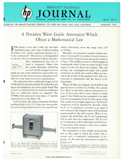
>> Download 1955-01 documenatation <<
Text preview - extract from the document
                                                       HEWLETT-PACKARD


                                            JOURNAL
                                            TECHNICAL INFORMATION FROM THE -hp- LABORATORIES                                                                       Vol. 6 No. 5

BLISHED BY THE HEWLETT-PACKARD COMPANY, 275 PAGE MILL ROAD, PALO ALTO, CALIFORNIA                                                                            JANUARY, 1955


                                     A Precision Wave Guide Attenuator Which
                                             Obeys a Mathematical Law
      FOR about a year and a half -hp- has been                            which collectively cover the range from 3.95
           manufacturing a new type of direct-reading                      to 18 kmc.
      precision wave guide attenuator known as a                              Basically, the attenuator consists of three sec
      rotary attenuator*. This device is distinguished                     tions of wave guide in tandem. In each section a
      by the fact that its attenuation follows a predict                   resistive film is placed across the guide as shown
                       able, mathematical law not re                       in Fig. 2. The middle section is a short length of
                       lated to frequency. Other than                      round guide which is free to rotate axially with
                       the cutoff attenuator which has                     respect to the two fixed end sections. The end
                       several disadvantages in wave                       sections are rectangular-to-round wave guide
      guide use, this rotary attenuator is generally con                   transitions in which the resistive films are nor
      sidered to be the most accurate attenuator avail                     mal to the E field of the applied wave. The con
      able for wide band microwave applications.                           struction is symmetrical and the device is bi
          The attenuator has a calibrated range of 0 to                    directional.
      50 db which is accurate within 2% of the db read                        When all films are aligned, the E field of the
      ing at any frequency in a wave guide band. This                     applied wave is normal to all films. No current
      accuracy is obtained directly from the calibrated                    then flows in the films, and no attenuation oc
      dial; no calibration charts are required. The                       curs. If the center film is now rotated to some
      VS WR of the attenuator is less than 1.15 and the                   angle 0, the E field can be considered to be split
      insertion loss is less than 1 db.                                   into two components: E sin 9 in the plane of the
          Until recently, the rotary attenuator has been                  film, and E cos 9 at right angles to it. The E sin 9
      produced only in 8.2-12.4 kmc size wave guide.                      component will be absorbed by the film, while
      It is now being produced in five wave guide sizes                   the E cos 9 component, oriented at an angle 6
                                                                          with respect to the original wave, will be passed
                                                                          unattenuated to the third section. When it en
                                                                          counters the third film, the E cos 9 component
                                                                          will be split into two components. The E cos 9
                                                                          sin 9 component will be absorbed, and the E cos2
◦ Jabse Service Manual Search 2026 ◦ Jabse Pravopis ◦ onTap.bg ◦ Other service manual resources online : Fixya ◦ eServiceinfo