Service Manuals, User Guides, Schematic Diagrams or docs for : Agilent journals 1955-06
<< Back | HomeMost service manuals and schematics are PDF files, so You will need Adobre Acrobat Reader to view : Acrobat Download Some of the files are DjVu format. Readers and resources available here : DjVu Resources
For the compressed files, most common are zip and rar. Please, extract files with Your favorite compression software ( WinZip, WinRAR ... ) before viewing. If a document has multiple parts, You should download all, before extracting.
Good luck. Repair on Your own risk. Make sure You know what You are doing.
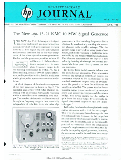
Image preview - the first page of the document
>> Download 1955-06 documenatation <<
Text preview - extract from the document
                                                             HEWLETT-PACKARD


                                        JOURNAL
                                        T E C H N I C A L    I N F O R M A T I O N   F R O M   T H E   - h p -   L A B O R A T O R I E S


.ISHED CALIFORNIA THE HEWLETT-PACKARD COMPANY, 275 PAGE MILL ROAD, PALO ALTO, CALIFORNIA                                                                                             JUNE, 1955


             The New -hp- 15-21 KMC 10 MW Signal Generator
             THE NEW -hp- 15-21 kilomegacycle signal                                  generators, a direct-reading frequency dial is
                  generator is designed as a general-purpose                          obtained by mechanically tracking the resona
             instrument which will give engineers working                             tor plunger with repeller voltage. The fre
             in the 1 5-2 1 kmc region the same conveniences                          quency range is covered by using parts of two
             and accuracy that have led to the wide accep                             modes, and mode switching is performed auto
             tance of the other -hp- microwave generators.                            matically by the repeller tracking mechanism.
             To this end the generator provides at least 10                           The klystron temperatures are kept at a low
                                milliwatts ( + 10 dbm) of max                        value by drawing air through the louvred por
                                imum output over its com                              tion of the front panel directly across the tube
                                plete frequency range, is di                          and resonator.
             rect-reading in frequency to within 1%, has a                               R-f power from the klystron is fed to a sim
             direct-reading, accurate 100 db output attenu                           ple uncalibrated attenuator. This attenuator
             ator, and is provided with a flexible modulator                         serves as the power set control and permits the
             which gives pulse, square-wave or f-m modu                               attenuator output to be standardized to the
             lation.                                                                 nominal maximum output value of 10 milli
                A block diagram of the circuit arrangement                           watts (in practice, at least 20 milliwatts are
             of the new generator is shown in Fig. 2. The                            usually obtainable). The power level at the at
             oscillator uses a type V40B reflex klystron op                          tenuator output is then monitored by a temper
             erating with an external waveguide resonator                            ature- and sensitivity-compensated thermistor
             which is tuned by a non-contacting type plun                            bridge. The power sample for the bridge is
             ger. The number of times the oscillator is tuned                        split from the main output by a specially-de
             through its frequency range is thus essentially                         signed directional coupler of the -hp- multi-
             independent of tube life. As in the other -hp-                          hole type1'2.
                                                                                         Following the directional coupler is the main
                                                                                     output attenuator which is of the rotary type3.
                                                                                     This type of attenuator has advantages in that
                                                                                     it is not sensitive to frequency in this range, has
                                                                                     an attenuation which is controlled by a mathe
                                                                                     matical law, is accurate, and is mechanically
                                                                                     practical to construct. Since the attenuation
                                                                                     range of a single attenuator is less than that de
                                                                                     sirable in a quality signal generator, however,
                                                                                     the attenuator used is formed from two rotary
                                                                                     1 E. F. Barnett and J. K. Huntoo, "A Precision Directional Coupler Using
                                                                                      Multi-Hole Coupling," Hewlett-Packard Journal, Volume 3, No. 7-8,
                                                                                      March-April, 1952.
                                                                                     - E. F. Barnett, "More About the -hp- Precision Directional Couplers,"
                                                                                       Hewlett-Packard Journal, Vol. 4, No. 5-6, January-February, 1953.
            Fig. 1. New -hp- Model 628A Signal Generator operates
                                                                                     3 B. P. Hand, "A Precision Wave Guide Attenuator Which Obeys a
            from 15 to 21 kmc, provides at least 10 milliwatts over                   Mathematical Law," Hewlett-Packard Journal, Vol. 6, No. 5, Jan
                                complete band.                                        uary, 1955.


   P R I N T E D   I N   U . S . A .                                                                                        C O P Y R I G H T   1 9 5 5   H E W L E T T - P A C K A R D   C O .
◦ Jabse Service Manual Search 2026 ◦ Jabse Pravopis ◦ onTap.bg ◦ Other service manual resources online : Fixya ◦ eServiceinfo