Service Manuals, User Guides, Schematic Diagrams or docs for : Agilent journals 1956-02
<< Back | HomeMost service manuals and schematics are PDF files, so You will need Adobre Acrobat Reader to view : Acrobat Download Some of the files are DjVu format. Readers and resources available here : DjVu Resources
For the compressed files, most common are zip and rar. Please, extract files with Your favorite compression software ( WinZip, WinRAR ... ) before viewing. If a document has multiple parts, You should download all, before extracting.
Good luck. Repair on Your own risk. Make sure You know what You are doing.
Image preview - the first page of the document
>> Download 1956-02 documenatation <<
Text preview - extract from the document
                                                                   HEWLETT - PACKARD

                                                  JOURNAL
                                                 TECHNICAL INFORMATION FROM THE -dp- LABORATORIES                                                                Vol. 7 No. 6

BLISHED BY THE HEWLETT-PACKARD COMPANY, 275 PAGE MILL ROAD, PALO ALTO, CALIFORNIA                                                                           FEBRUARY, 1956


                                          Three New -hp- Audio Oscillators

           YEAR after year the simple, reliable -hp-                                    ing of the frequency dials. Rotary switches use
                R-C audio oscillator remains one of the                                 bar type knobs for ease of switching.
           work horses of the electronics laboratory. The                                        /. HIGH-OUTPUT HIGH-QUALITY AUDIO
           Hewlett-Packard Company has always taken                                                 TEST OSCILLATOR (20 CPS-20 KC)
                            special pride in the R-C oscilla                               The new Model 20 1C oscillator at the left in
                            tor and has always striven to                               Fig. 1 is designed for testing higher-quality
                            see that suitable R-C oscillators                           audio systems. The instrument operates over
           are provided for every purpose.                                              the range from 20 cps to 20 kc and provides a
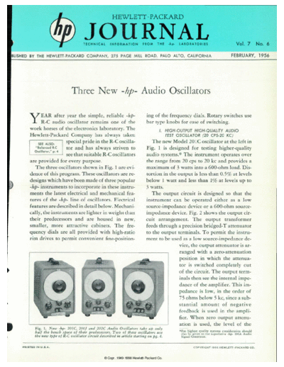
             The three oscillators shown in Fig. 1 are evi                              maximum of 3 watts into a 600-ohm load. Dis
           dence of this program. These oscillators are re                              tortion in the output is less than 0.5% at levels
           designs which have been made of three popular                                below 1 watt and less than 1% at levels up to
           -hp- instruments to incorporate in these instru                              3 watts.
           ments the latest electrical and mechanical fea                                  The output circuit is designed so that the
           tures of the -hp- line of oscillators. Electrical                            instrument can be operated either as a low
           features are described in detail below. Mechani                              source-impedance device or a 600-ohm source-
           cally, the instruments are lighter in weight than                            impedance device. Fig. 2 shows the output cir
           their predecessors and are housed in new,                                    cuit arrangement. The output transformer
           smaller, more attractive cabinets. The fre                                   feeds through a precision bridged-T attenuator
           quency dials are all provided with high-ratio                                to the output terminals. To permit the instru
           rim drives to permit convenient fine-position-                               ment to be used as a low source- impedance de
                                                                                                        vice, the output attenuator is ar
                                                                                                        ranged with a zero- attenuation
                                                                                                        position in which the attenua
                                                                                                        tor is switched completely out
                                                                                                        of the circuit. The output term
                                                                                                        inals then see the internal impe
                                                                                                        dance of the amplifier. This im
                                                                                                        pedance is low, in the order of
                                                                                                        75 ohms below 5 kc, since a sub
                                                                                                        stantial amount of negative
                                                                                                        feedback is used in the ampli
                                                                                                        fier. When zero output attenu
                                                                                                        ation is used, the level of the
                    Fig. only New -hp- 201 C , 200 J and 202C Audio Oscillators take up only
                    half the bench space of their predecessors. Two of these oscillators use
◦ Jabse Service Manual Search 2026 ◦ Jabse Pravopis ◦ onTap.bg ◦ Other service manual resources online : Fixya ◦ eServiceinfo