Service Manuals, User Guides, Schematic Diagrams or docs for : Agilent journals 1956-05
<< Back | HomeMost service manuals and schematics are PDF files, so You will need Adobre Acrobat Reader to view : Acrobat Download Some of the files are DjVu format. Readers and resources available here : DjVu Resources
For the compressed files, most common are zip and rar. Please, extract files with Your favorite compression software ( WinZip, WinRAR ... ) before viewing. If a document has multiple parts, You should download all, before extracting.
Good luck. Repair on Your own risk. Make sure You know what You are doing.
Image preview - the first page of the document
>> Download 1956-05 documenatation <<
Text preview - extract from the document
                                                                   HEWLETT-PACKARD


                                             JOURNAL
                                             T E C H N I C A L   I N F O R M A T I O N   F R O M   T H E   - h p -   L A B O R A T O R I E S                                Vol.7 No. 9-10

PUBLISHED BY THE HEWLETT-PACKARD COMPANY, 275 PAGE MILL ROAD, PALO ALTO, CALIFORNIA                                                                                         MAY-JUNE, 1956


                             A New 10-15.5 KMC 10 MW Signal Generator
           THE new -hp- Model 626A SHF Signal Gen                                          frequency dial accurate within 1%, a direct-
                erator operates over the range from 10 to                                  reading attenuator with a 100 db range, and
           15.5 kilomegacycles and provides a high out                                     a flexible modulator that provides internal
           put of many milliwatts over this range. Al                                      square-wave, pulse or f-m modulation of the
           though the generator is rated as providing a                                    output signal. The new generator has been de
                                 maximum of at least 10 mil                                veloped as a companion to the recently-devel
                 SEE ALSO        liwatts over the whole                                    oped -hp- 15-21 kmc generator'.
            "Simple Regulated
             Power Supply", p. 3 range, it usually provides                                   Fig. 2 shows the generator's circuit arrange
            "Obtaining Balanced
             Square Waves", p. 4 more than 15 milliwatts at                                ment. The oscillator klystron operates with an
                                 all frequencies and over                                  external resonator which is tuned with a non-
           most of the range the output is in the 30- milli                                contacting type plunger. Oscillator tube life
           watt or higher region. The generator is thus                                    is thus unrelated to the number of times the
           valuable as a signal source for rough test work                                 instrument is tuned through its frequency
           as well as for reflectometer, slotted line, and re                              range. Repeller voltage is automatically
           ceiver applications.                                                            tracked with the frequency dial so that no re-
              In addition to its relatively high maximum                                   peller voltage adjustments are required.
           power output, the generator has the other fea                                      The path from the klystron to the output
           tures that make any signal generator conven                                     terminals is all contained in wave guide. The
           ient to use. These include a direct-reading                                     klystron is followed by an uncalibrated wave
                                                                                           guide attenuator which serves to adjust the
                                                                                           power level applied to the main calibrated at
                                                                                           tenuator. This reference level is designed to
                                                                                           be 10 milliwatts, and the attenuator calibration
                                                                                           is based on a 10-milliwatt reference level. As
                                                                                           mentioned earlier, however, much higher pow
                                                                                           ers can be obtained when desired by operating
                                                                                           the instrument with both attenuators set for
                                                                                           minimum loss. The level at the input to the
                                                                                           main attenuator is monitored by a compen
                                                                                           sated thermistor bridge which operates a panel
                                                                                           meter. A wave guide directional coupler of the
                                                                                           -hp- multi-hole type- splits off a sample of the
                                                                                           power applied to the output attenuator for
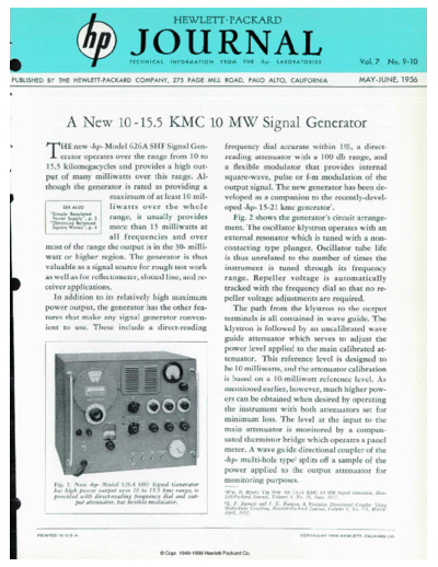
                  Fig. 1. New -hp- Model 6 26 A SHF Signal Generator
                                                                                           monitoring purposes.
                  has high power output over 10 to i 5.5 kmc range, is                      >Wm. Hew Myers, The New -lip- 15-21 KMC 10 MW Signal Generator, Hew
                  provided u'ith direct-reading frequency dial and out                      lett-Packard Journal, Volume ó, No. 10, June, 1955.
                          put attenuator, has flexible modulator.                           'E. F. Burnett and J. K. Hunton, A Precision Directional Coupler Using
                                                                                            Multi-Hole Coupling, Hewlett-Packard Journal. Volume 3, No 7-8 lUarc/i-
                                                                                            April, 1952.


      P R I N T E D   I N   U . S . A .                                                                                           C O P Y R I G H T   1 9 5 6   H E W L E T T - P A C K A R D   C O .
◦ Jabse Service Manual Search 2026 ◦ Jabse Pravopis ◦ onTap.bg ◦ Other service manual resources online : Fixya ◦ eServiceinfo