Service Manuals, User Guides, Schematic Diagrams or docs for : Agilent journals 1956-07
<< Back | HomeMost service manuals and schematics are PDF files, so You will need Adobre Acrobat Reader to view : Acrobat Download Some of the files are DjVu format. Readers and resources available here : DjVu Resources
For the compressed files, most common are zip and rar. Please, extract files with Your favorite compression software ( WinZip, WinRAR ... ) before viewing. If a document has multiple parts, You should download all, before extracting.
Good luck. Repair on Your own risk. Make sure You know what You are doing.
Image preview - the first page of the document
>> Download 1956-07 documenatation <<
Text preview - extract from the document
                                                    HEWLETT-PACKARD

                                         JOURNAL
                                         TECHNICAL INFORMATION FROM THE -ftp- LABORATORIES                                               Vol. 7 No. 11 -12
                                                                                                                                        ^B^^^^^^^^^^H
iLISHED BY THE HEWLETT-PACKARD COMPANY, 275 PAGE MILL ROAD, PALO ALTO, CALIFORNIA                                                    JULY-AUGUST, 1956


                                       A 0-1.1 MC Frequency Counter
                                        with Time Interval Markers
            ANEW -hp- frequency counter has been                         cies, measure the period or 10-period average
                 designed which incorporates a number                    of lower frequencies, and act as a secondary
            of new features and which also includes the                  frequency standard by making available ex
            previously-developed features that have al                   ternally an accurately-controlled 100 kc fre
            ways given -hp- counters their leading posi                  quency.
            tion in the field. The new counter measures                     The basic circuit arrangement of the new
            frequencies from 0 to 1.1 megacycles and                     counter is shown in Fig. 3. The frequency to
                               time intervals from 3 mi                  be measured is passed through a gate circuit
                               croseconds to 27.8 hours.                 which is opened by a precision time-base cir
                               These ranges suit the in                  cuit for an accurately-controlled interval
            strument to much of the frequency-measur                     such as 1 second. A panel switch permits the
            ing work that goes on in a typical electronics               operator to select in decade steps any of five
            laboratory as well as to almost any of the                   gate times from 1 millisecond to 10 seconds.
            mechanical applications where a counter is                   The cycles of the frequency to be measured
            useful such as in measuring rpm, velocity,                   that pass through the gate are then applied
            flow rates, etc. Besides measuring frequency                 to a series of six decade counting units which
            and time intervals, the instrument will also                 indicate in illuminated numerals the num
            count events, i.e., totalize, for as long as de              ber of cycles that have occurred while the
            sired, form the ratio of two external frequen                gate was open. The measured frequency can


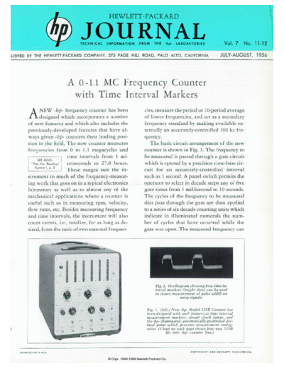
                                                                                 Fig. 2. Oscillogram showing how time in
                                                                                 terval markers (bright dots) can be used
                                                                                 to insure measurement of pulse width on
                                                                                                noisy signals.

                                                                           Fig. 1. (left.) New -hp- Model 523B Counter has
                                                                           been designed with such features as time interval
                                                                           measurement markers, circuit check lamps, and
                                                                           the -hp- illuminated, automatically-positioned dec
                                                                           imal point which prevents measurement ambig
                                                                           uities. (Chart on back page shows how new 523B
                                                                                       fits into -hp- counter line.)


   P R I N T E D   I N   U . S . A .                                                                C O P Y R I G H T   1 9 5 6   H E W L E T T - P A C K A R D   C O .
◦ Jabse Service Manual Search 2026 ◦ Jabse Pravopis ◦ onTap.bg ◦ Other service manual resources online : Fixya ◦ eServiceinfo