Service Manuals, User Guides, Schematic Diagrams or docs for : Agilent journals 1959-05
<< Back | HomeMost service manuals and schematics are PDF files, so You will need Adobre Acrobat Reader to view : Acrobat Download Some of the files are DjVu format. Readers and resources available here : DjVu Resources
For the compressed files, most common are zip and rar. Please, extract files with Your favorite compression software ( WinZip, WinRAR ... ) before viewing. If a document has multiple parts, You should download all, before extracting.
Good luck. Repair on Your own risk. Make sure You know what You are doing.
Image preview - the first page of the document
>> Download 1959-05 documenatation <<
Text preview - extract from the document
                                                                         HEWLETT-PACKARD


V   " f   T E C H N I C A L
                                                         JOURNAL
                                               I N F O R M A T I O N    F R O M      T H E    - h p -    L A B O R A T O R I E S
                                                                                                                                                                       )l. 10, No. 9- 10

PUBLISHED BY THE HEWLETT-PACKARD COMPANY, 275 PAGE MILL ROAD, PALO ALTO, CALIFORNIA                                                                                MAY -JUNE, 1959


                                    A Clip -On Oscilloscope Probe
                            for Measuring and Viewing Current Waveforms
           A though current is a fundamental quantity                                          tion the general problem of measuring alter
                 in electronic circuitry and accurate knowl                                    nating currents is made much more convenient
           edge of it is valuable, it is a quantity that has                                   by a new oscilloscope probe which permits
           always been rather inconvenient to measure                                          both viewing and measuring alternating cur
           and in at least one important case quite diffi                                      rents merely by clipping the probe around the
           cult. This is the case of alternating currents in                                   current conductor. The probe operates with the
           circuits elevated from ground. Here, to use a                                       -hp- Model 150A Oscilloscope and a new plug-
           current meter involves at best the trouble of                                       in amplifier to measure and display currents
           opening the circuit, while the meter, when con                                      over an amplitude range from 1 milliampere
           nected, will usually not indicate such often-                                       to 15 amperes peak-to-peak and over a fre
           needed information as the current's peak value.                                     quency range from below 500 cps to 8 mega
           At the same time to measure the current wave                                        cycles. In the case of sinusoidal currents, wave
           form in such circuits with an oscilloscope has                                      forms down to about 50 cps can be displayed.
           required the combination of a suitable circuit                                         Electrically, the probe consists of a wide-
           resistance to connect across and an oscilloscope                                    range current transformer with a split core
           with a differential input of adequate range, a                                      which is mechanically opened and closed by
           combination often not available.                                                    flanges on the probe body in the manner proved
              These problems are overcome and in addi                                          popular in other -hp- probes. When the probe


                                                                                                                                                                        PLATE
                                                                                                                                                                       VOLTAGE


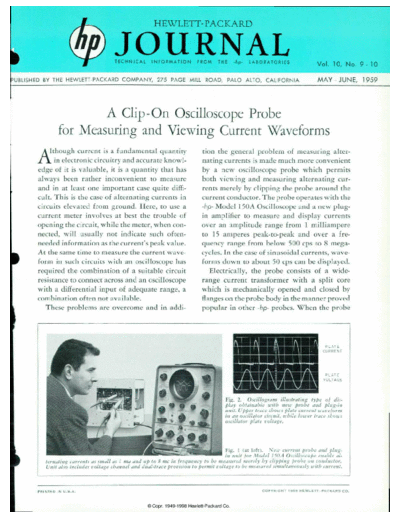
                                                                                                         Fig. 2. Oscillogram illustrating type of dis
                                                                                                         play obtainable with new probe and plug-in
                                                                                                         unit. V pper trace shows plate current waveform
                                                                                                         in an oscillator circuit, while lower trace shows
                                                                                                         oscillator plate voltage.


                                                                                              Fig. 1 (at left). N'e/i' current probe and plug-
                                                                                              in unit for Model 1 W A Oscilloscope enable al
                 ternating currents as small as I ma and up to 8 me in frequency to be measured merely by clipping probe on conductor.
                 Unit also simultaneously roltage channel and dual-trace provision to permit foliage to be measured simultaneously with current.


           P R I N T E D   I N   U . S . A .                                                                            C O P Y R I G H T   1 9 5 9   H E W L E T T - P A C K A R D   C O .
◦ Jabse Service Manual Search 2026 ◦ Jabse Pravopis ◦ onTap.bg ◦ Other service manual resources online : Fixya ◦ eServiceinfo