Service Manuals, User Guides, Schematic Diagrams or docs for : Akai ADV ADV-85DR ADV-85DR
<< Back | HomeMost service manuals and schematics are PDF files, so You will need Adobre Acrobat Reader to view : Acrobat Download Some of the files are DjVu format. Readers and resources available here : DjVu Resources
For the compressed files, most common are zip and rar. Please, extract files with Your favorite compression software ( WinZip, WinRAR ... ) before viewing. If a document has multiple parts, You should download all, before extracting.
Good luck. Repair on Your own risk. Make sure You know what You are doing.
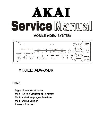
Image preview - the first page of the document

>> Download ADV-85DR documenatation <<
Text preview - extract from the document
                MOBILE VIDEO SYSTEM


    MODEL: ADV-85DR


Note:

 Digital Audio Out-Coaxial
 Multi-subtitle Languages Function
 Multi-audio Languages Function
 Multi-angle Function
 Parental Control
                                                                       CONTENTS

                                                                                                                                                           Page
Disassembly Instructions.................................................................................................................................... 3
Disassembly Diagram......................................................................................................................................... 4
Block Diagram .................................................................................................................................................... 5
Printed Circuit Board........................................................................................................................................... 6
Wiring Diagram ................................................................................................................................................... 12
Exploded View .................................................................................................................................................... 13
Exploded View Parts List .................................................................................................................................... 14
Schematic Diagram ............................................................................................................................................ 15
Electrical Parts List ............................................................................................................................................. 19
Specifications...................................................................................................................................................... 26


                                                                                    2
                               DISASSEMBLY INSTRUCTIONS

1. Remove two screws (A) from each side of the top cabinet and remove three screws (B) located on the rear of
   the top cabinet then remove the Top Cabinet.


2. Remove four screws (C) located on the under the bottom cabinet then remove four Rubber Foot DVD171.


4. Remove two screws (D) located on the under the bottom cabinet and remove two screws (E) from each side
   of the top panel then remove the Top Panel.


5. Remove two screws (F) from the deck front bracket and remove two screws (G) from the deck rear bracket
   then remove the Main Board and the Bottom Cabinet.


6. Remove two screws (H) from the deck front bracket then remove the Deck Front Bracket.


7. Remove two screws (I) from the deck rear bracket then remove the Deck and the Deck Rear Bracket.


                                                     3
DISASSEMBLY DIAGRAM


         4
BLOCK DIAGRAM


      5
             PRINTED CIRCUIT BOARDS
MAIN BOARD


                     TOP VIEW


                        6
MAIN BOARD


             BOTTOM VIEW


                  7
KEY BOARD


            TOP VIEW


               8
KEY BOARD


            BOTTOM VIEW


                 9
REMOTE BOARD


               TOP VIEW


                  10
REMOTE BOARD


               BOTTOM VIEW


                   11
WIRING DIAGRAM


      12
EXPLODED VIEW


     13
                                 EXPLODED VIEW PARTS LIST

Ref. No.                             Description         RS Part No.   Mfr's Part No.
   1       Ring (S. OPC1202)                                           51-H2020-80A
   2       Panel Top W/O TV (S. OPC1202)                               51-K2020-84Y
   3       Top Cover (S. OPC1202)                                      61-H2002-80
   4       Bottom Cabinet W/O TV (S. OPC1202)                          61-K2001-81B
   5       Main PCB Paper                                              43-H2001-00
   6       Main Board                                                  11-02014-007
   7       DVD MECH. Slot Type (Hop-1200W)                             94-02682-00
   8       Deck Front Bracket                                          39-B2001-01
   9       Deck Rear Bracket                                           39-B2002-01
  10       Key Board                                                   11-02014-337
  11       Shade                                                       81-69005-02
  12       CD Windows Sheet                                            43-A3101-00
  13       Panel Top Decoration (EA-Silver)                            52-K2022-90E
  14       Panel Top Decoration (EA-Silver)                            52-K2023-90E
  15       Function Key (E-Silver)                                     52-K2027-90E
  16       MENU/Power Key (L-Up) (S. OPC0000)                          52-K2026-01
  17       EJ/SEL Knob (L-Up) (E-Silver)                               52-K2028-91E
  18       Stop/Next Knob (L-Up) (E-Silver)                            52-K2029-91E
  19       Play/Pause/PREV Knob (L-Up) (E-Silver)                      52-K2030-91E
  20       SEL/Source Knob (L-Up) (E-Silver)                           52-K2024-90E
  21       INDEX Light                                                 52-K2031-00
  22       1AVIN2/DVD Light                                            52-K2032-00
  23       IR Lens                                                     52-K2025-50R
  24       Lighting Sleeve                                             52-K2021-00
  25       Rubber Foot (Clear)                                         81-D1701-01
  26       Screw
◦ Jabse Service Manual Search 2024 ◦ Jabse Pravopis ◦ onTap.bg ◦ Other service manual resources online : Fixya ◦ eServiceinfo