Service Manuals, User Guides, Schematic Diagrams or docs for : CANON Copiers GP 405 ServBull ServBullGP405 acc-177

<< Back | Home

Most service manuals and schematics are PDF files, so You will need Adobre Acrobat Reader to view : Acrobat Download Some of the files are DjVu format. Readers and resources available here : DjVu Resources
For the compressed files, most common are zip and rar. Please, extract files with Your favorite compression software ( WinZip, WinRAR ... ) before viewing. If a document has multiple parts, You should download all, before extracting.
Good luck. Repair on Your own risk. Make sure You know what You are doing.


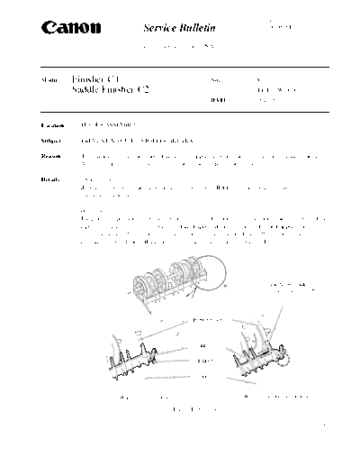
Image preview - the first page of the document
acc-177


>> Download acc-177 documenatation <<

Text preview - extract from the document
                                             Service Bulletin                                       COPIER


                                             Issued by Canon Europa N.V.


Model      :   Finisher-C1                                                   No.:            Acc-177
               Saddle Finisher-C2                                                            (FF-T01-W-000075-01)
                                                                             DATE:           08.10.99


Location       :   FEEDER ASSEMBLY

Subject        :   PREVENTING GUIDE STOPPER BREAKAGE

Reason         :   To communicate that the shape of the guide stopper has been changed to prevent it from breaking.
                   Also, to communicate field measures to take if the stopper breaks in the field.

Details        :   
                   If the guide stopper breaks, there are cases where the buffer roller stops the copy paper, and a
                   stationary jam occurs.

                   
                   The guide stopper determines the stop position of the flapper, but this stopper breaks as a result of the
                   repeated opening and closing operation of the flapper. If the stopper breaks, the flapper makes
                   contact with the buffer roller, and a load is placed on the rotation of the buffer roller. In the worst
                   case, the rotation of the buffer roller is halted, and a stationary jam occurs. (Fig. 1)


                                                                                                   The flapper makes
                                                                                                   contact with the buffer
                                                                                                   roller.


                                                                     Buffer roller


                                                                     Flapper

                                                                     Stopper

                                                                     Guide


                                  [When there is a stopper]                            [When the stopper has broken]

                                                              Fig. 1 Feeder assembly

                                                                                                                       -1/5-
                                                                                                             Acc-177

             
             Durability of the guide stopper was improved by strengthening it with the addition of a rib (Fig. 2).

                                   [Old guide]                                [New guide]
                                                                                                Stopper strengthened by
                                                                                                the addition of a rib
                                                       Stopper


                                                              Fig. 2

Servicing   : Perform the measures below to deal with the previously-mentioned symptoms in the field.
              Attach the field measure part STOP, GUIDE (FB4-9693-000), following the procedure shown below,
              as a field measure (Fig. 3).

                                                                                                          Flapper


                             Upper cover                Rear cover


                                                                                                             Guide
                  (Front
                  cover                                                              [Before attaching]
                   side)
                                                                                                          Flapper


                                                      Guide                                                  Guide
                                                                                                             stopper

                                                                                                             Guide
                                            Guide stopper
                                                                                      [After attaching]

                                              Fig. 3 Section to stick the guide stopper


                                                                                                              -2/5-
                                                                                                           Acc-177


1) Prepare the guide stopper (FB4-9693-000), lint free paper, and alcohol.
2) Turn the main power switch off, and unplug the power supply.
3) Pull the finisher away from the main copier body.
4) Remove the separation tray, and open the upper cover (Fig. 4).

                Interrupt tray

                 Upper cover

                                                                (Main body side)


                                                 Fig. 4

5) Peel off the paper from the back of the tape which is stuck to the inner side of the guide stopper
   and place the tape side on top of the rear cover.
6) Take lever 2, which is on the front cover side, between the fingers of the left hand, and lift up the
   buffer roller. Once it is lifted up, hold it in that position (Fig. 5).

                                 Lever 2                                              Upper cover

          Buffer roller cover

                                                                                   (Rear cover side)
            (Front cover side)


                                                                                   Buffer roller


                                             (Main body side)
                                                     Fig. 5

7) With the right hand, clean out the dirt from the inner side of the guide with lint free paper
   dampened with alcohol.
                                     Guide      Rear cover
 Upper cover                                                                                       Guide


                                                                                                   Rear cover


                  (Main body side)

                                     Buffer roller                                           Clean the inner side
                                                                                             of the guide

                                                     Fig. 6

                                                                                                           -3/5-
                                                                                                          Acc-177

8) With the left hand holding the buffer roller up, open the flapper by pressing down the upper
   flapper assembly with the finger in the direction of the delivery tray, and hold it in this position
   (Fig. 7).
                                (Direction of the delivery tray)
                                                                               Upper part of the flapper


                                                                                Buffer roller


                                                    Fig. 7

9) When sticking the guide stopper to the guide, the protruding section on the inner side of the guide
    stopper must be inserted into the square opening on the guide. Therefore, perform the following
    operations.
i) Hold the side A of the guide stopper between the fingers, and face the side B toward the square opening
    on the guide (Fig. 8).
ii) While taking care that the side A of the guide stopper does not rise causing the guide stopper tape and
    the guide to make contact, pass the side B of the guide stopper through the space between the flapper
    and the guide, pushing it in the direction of the arrow 1 (Fig. 9) until it stops. After this, slowly lay the
    side A onto the guide.

   Upper cover
                 Rear cover
                                Square opening in the
                                guide
                                                    Upper
                                                    cover                                           Flapper


                                                                                                     Guide stopper

                                                                               
             Protruding
             section on inner
             side


◦ Jabse Service Manual Search 2026 ◦ Jabse PravopisonTap.bg ◦ Other service manual resources online : FixyaeServiceinfo