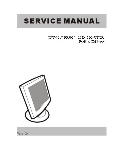
Service Manuals, User Guides, Schematic Diagrams or docs for : COMPAQ Monitor TFT-5017, FP5017 COMPAQ+TFT-5017-FP5017
<< Back | HomeMost service manuals and schematics are PDF files, so You will need Adobre Acrobat Reader to view : Acrobat Download Some of the files are DjVu format. Readers and resources available here : DjVu Resources
For the compressed files, most common are zip and rar. Please, extract files with Your favorite compression software ( WinZip, WinRAR ... ) before viewing. If a document has multiple parts, You should download all, before extracting.
Good luck. Repair on Your own risk. Make sure You know what You are doing.
Image preview - the first page of the document

>> Download COMPAQ+TFT-5017-FP5017 documenatation <<
Text preview - extract from the document
    SERVICE MANUAL

          TFT-5017/FP5017 LCD MONITOR
                           FOR COMPAQ


C


Ver: 00
THESE DOCUMENTS ARE FOR REPAIR SERVICE INFORMATION ONLY. EVERY
REASONABLE EFFORT HAS BEEN MADE TO ENSURE THE ACCURACY OF THIS
MANUAL; WE CANNOT GUARANTEE THE ACCURACY OF THIS INFORMATION
AFTER THE DATE OF PUBLICATION AND DISCLAIMS RE LIABILITY FOR CHANGES,
ERRORS OR OMISSIONS,

MANUFACTURE DATA: Jun 22 2002


                                  1
                                                TABLE OF CONTENTS
PAGE
  1. SPECIFICATIONS ....................................................................................................          3
     1-1  GENERAL SPECIFICATIONS ....................................................................                             3
     1-2 LCD MONITOR DESCRIPTION ..................................................................                               4
     1-3  INTERFACE CONNECTOR ........................................................................                            4

   2.    PRECAUTION AND NOTICES ................................................................................                  5
         2-1 ASSEMBLY PRECAUTION .........................................................................                        5
         2-2 OPERATIONG PRECAUTION .....................................................................                          5
         2-3 STORAGE PRECAUTION ...........................................................................                       5
         2-4 HIGH VOLTAGE WARNING .......................................................................                         5

   3.    OPERATING INSTRUCTIONS ................................................................................                   6

   4.    ADJUSTMENT ..........................................................................................................    7
         4-1 ADJUSTMENT CONDITIONS AND PRECAUTIONS ...............................                                                7
         4-2 ADJUSTMENTS METHOD ...........................................................................                       7
         4-3 FRONT PANEL CONTROL KNOBS ............................................................                               8

   5.    CIRCUIT DESCRIPTION ..........................................................................................           9
         5-1 SPECIAL FUNCTION WITH PRESS KEY ......................................                                               9
         5-2  SIMPLE INTRODUCTION ABOUT TFT5017/FP5017 CHIPSET .........                                                          9

   6.    TROUBLE SHOOTING CHART ..............................................................................                   10

   7.    MECHANICAL OF CABINET FRONT DIS-ASSEMBLY......................................                                           72

   8.    PARTS LISTING .....................................................................................................     73

   9.    POWER SYSTEM AND CONSUMPTION CURRENT............................................                                        107

   10. PCB LAYOUT ...................................................................................................            108

   11. SCHEMATIC DIAGRAM ........................................................................................                109


                                                                  2
                                    1. SPECIFICATIONS FOR LCD MONITOR

1-1        General specifications
      1.    LCD-PANEL :
            Active display area       15 inches diagonal
            Pixel pitch               0.297 mm x 0.297 mm
            Pixel format              1024 x 768 RGB vertical stripe arrangement

      2.    Display Color :
            6-bit, 262144 colors

      3.   External Controls :
           Horizontal Position, Vertical Position, Clock, Clock Phase and Auto Adjustment
           Power On/Off, Brightness, Contrast, Color Select (6500
◦ Jabse Service Manual Search 2024 ◦ Jabse Pravopis ◦ onTap.bg ◦ Other service manual resources online : Fixya ◦ eServiceinfo