Service Manuals, User Guides, Schematic Diagrams or docs for : Casio Cameras CASIO_QV_2400UX
<< Back | HomeMost service manuals and schematics are PDF files, so You will need Adobre Acrobat Reader to view : Acrobat Download Some of the files are DjVu format. Readers and resources available here : DjVu Resources
For the compressed files, most common are zip and rar. Please, extract files with Your favorite compression software ( WinZip, WinRAR ... ) before viewing. If a document has multiple parts, You should download all, before extracting.
Good luck. Repair on Your own risk. Make sure You know what You are doing.
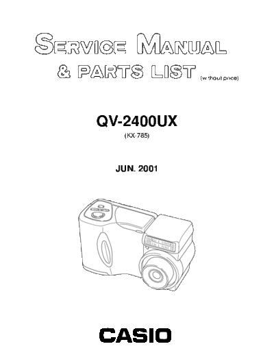
Image preview - the first page of the document
>> Download CASIO_QV_2400UX documenatation <<
Text preview - extract from the document
                          (without price)


        QV-2400UX
           (KX-785)


          JUN. 2001


INDEX                 R
                                                                 CONTENTS

SPECIFICATIONS ....................................................................................................................................... 1
BLOCK DIAGRAM ...................................................................................................................................... 3
ADJUSTMENT ............................................................................................................................................ 4
 s Preparation .......................................................................................................................................... 4
 1. PROGRAM LOADING .......................................................................................................................... 5
   1-1. Important notice ............................................................................................................................ 5
   1-2. To load the program ..................................................................................................................... 5
 2. Program version upgrading .............................................................................................................. 7
   2-1. How to confirm the program (graphic menu) version .............................................................. 7
   2-2. Upgrading using CF card ............................................................................................................ 8
 3. Test mode ........................................................................................................................................... 9
   3-1. Booting ......................................................................................................................................... 9
   3-2. Item for testing ............................................................................................................................. 9
 4. Adjustment ....................................................................................................................................... 11
   4-1. Color adjustment data writing .................................................................................................. 11
     4-1-1. Note ...................................................................................................................................... 11
     4-1-2. The example which must be adjusted .............................................................................. 11
     4-1-3. To replace the lens ass'y ................................................................................................... 11
     4-1-4. To replace CMD-PCB .......................................................................................................... 13
   4-2. Flash adjustment ....................................................................................................................... 15
   4-3. Flash operation and recharge operation ................................................................................. 16
   4-4. Current consumption ................................................................................................................ 17
   4-5. VCOM DC adjustment ................................................................................................................ 18
   4-6. Operation check ......................................................................................................................... 20
 5. D-PCB Assy ...................................................................................................................................... 21
   5-1. VCO free run frequency adjustment ........................................................................... 21
    5-2. VCOM AC adjustment and VCOM DC coarse adjustment ........................................ 21
    5-3. RGB AMP and Sub-Brightness voltage setting adjustment ..................................... 22
    5-4. Contrast and Brightness voltage setting adjustment ............................................... 23
    5-5. TINT setting adjustment ............................................................................................... 24
  6. PW-PCB Assy ................................................................................................................................... 25
    6-1. VCC3, VCC3-MD, VCC5, VCC7.5, EVCC3 Voltage check .......................................... 25
    6-2. VCC15, VEE7.5 Adjustment ......................................................................................... 25
DISASSEMBLY/ASSEMBLY .................................................................................................................... 26
EXPLODED VIEW ..................................................................................................................................... 36
PARTS LIST .............................................................................................................................................. 37
PRINTED CIRCUIT BOARDS ................................................................................................................... 40
SCHEMATIC DIAGRAMS ......................................................................................................................... 45
                                                  SPECIFICATIONS
File Format                       Still images (including panoramas): JPEG (Exif. Ver. 2.1) / TIFF, DCF standard (Design rule for
                                  Camera File system), DPOF compatible Movies: AVI (Motion JPEG)
Recording Medium                  CompactFlash card (Type I/II), IBM Microdrive
Recorded Image Size               1600 x 1200 pixels, 800 x 600 pixels
Standard Memory Capacity, Number of Image Files, Computer Output Image Size

                                                                Still
                                                                                    Number of images
           Image size
                            Quality           File size                   8MB                           340MB
             (pixels)
                                                                  Compact Flash card                   Microdrive
              1600           FINE          850KB/image                  8 images                     401 images
                x           NORMAL         600KB/image                  11 images                    562 images
              1200        ECONOMY          350KB/image                  19 images                    943 images
               800           FINE          200KB/image                  33 images                   1587 images
                x           NORMAL         150KB/image                  43 images                   2054 images
               600        ECONOMY          120KB/image                  53 images                   2494 images

                                                  Movie (320 x 240 pixels)
           Storage Capacity               Approximately 300KB/second
           Recording Time                 16 seconds per movie
◦ Jabse Service Manual Search 2026 ◦ Jabse Pravopis ◦ onTap.bg ◦ Other service manual resources online : Fixya ◦ eServiceinfo