Service Manuals, User Guides, Schematic Diagrams or docs for : Casio Cameras CASIO_QV_3000EX
<< Back | HomeMost service manuals and schematics are PDF files, so You will need Adobre Acrobat Reader to view : Acrobat Download Some of the files are DjVu format. Readers and resources available here : DjVu Resources
For the compressed files, most common are zip and rar. Please, extract files with Your favorite compression software ( WinZip, WinRAR ... ) before viewing. If a document has multiple parts, You should download all, before extracting.
Good luck. Repair on Your own risk. Make sure You know what You are doing.
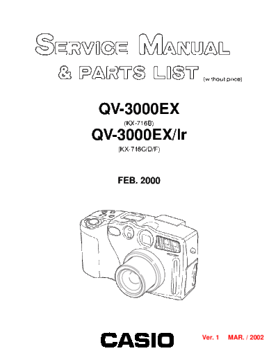
Image preview - the first page of the document

>> Download CASIO_QV_3000EX documenatation <<
Text preview - extract from the document
                               (without price)


        QV-3000EX
            (KX-716B)

        QV-3000EX/Ir
           (KX-716C/D/F)


           FEB. 2000


                               Ver. 1   MAR. / 2002
INDEX                      R
                                                                 CONTENTS

SPECIFICATIONS ....................................................................................................................................... 1
To distinguish the model .......................................................................................................................... 3
BLOCK DIAGRAM ...................................................................................................................................... 4
CIRCUIT BLOCK ......................................................................................................................................... 5
ADJUSTMENT ............................................................................................................................................ 6
  1. Program version upgrading .............................................................................................................. 7
    1-1. How to confirm the program (graphic menu) version .............................................................. 7
    1-2. Upgrading procedure using the CompactFlash card ............................................................... 7
    1-3. Upgrading procedure using the PC link cable .......................................................................... 8
  2. Test mode ........................................................................................................................................... 9
    2-1. Booting ......................................................................................................................................... 9
    2-2. Item for testing ............................................................................................................................. 9
  3. Product conditions .......................................................................................................................... 11
    3-1. Color adjustment data writing .................................................................................................. 11
    3-2. Flash adjustment ....................................................................................................................... 19
    3-3. Flash operation and recharge operation ................................................................................. 20
    3-4. Current consumption ................................................................................................................ 21
    3-5. VCOM DC adjustment ................................................................................................................ 22
    3-6. Operation check ......................................................................................................................... 23
  4. D-PCB Assy ...................................................................................................................................... 24
    4-1. VCO free run frequency adjustment ........................................................................................ 24
    4-2. VCOM AC adjustment and VCOM DC coarse adjustment ..................................................... 24
    4-3. RGB AMP, Sub bright adjustment ............................................................................................ 25
    4-4. Contrast, Bright adjustments ................................................................................................... 26
    4-5. Color adjustment ....................................................................................................................... 27
    4-6. TINT adjustment ......................................................................................................................... 28
  5. PW-PCB Assy ................................................................................................................................... 29
    5-1. VCC3, VCC3-M, VCC5, VCC7 Voltage check ........................................................................... 29
    5-2. VCC15, VEE7 Voltage check ..................................................................................................... 29
    5-3. BL drive voltage adjustment ..................................................................................................... 29
DISASSEMBLY/ASSEMBLY .................................................................................................................... 30
EXPLODED VIEW ..................................................................................................................................... 46
PARTS LIST .............................................................................................................................................. 47
PRINTED CIRCUIT BOARDS ................................................................................................................... 49
SCHEMATIC DIAGRAMS ......................................................................................................................... 55
                                                            SPECIFICATIONS
File Format                             Still images (including panoramas): JPEG (Exif. Ver. 2.1), DCF standard (Design rule for Camera
                                        File system), DPOF compatible, Movies: AVI
Recording Medium                        CompactFlash card (Type I/II)
Recorded image Size                     2048 x 1536 pixels, 1024 x 768 pixels
Standard Memory Capacity,Number of Image Files,Computer Output Image Size
                                                                      Still
             Image size                                                               Number of images
                              Quality           File size
               (pixels)                                         8 MB memory card      64MB memory card        340MB Microdrive
                 2048       FINE             1.4 MB/images          5 images             43 images               245 images
                  x        NORMAL             1 MB/images           6 images             60 images               342 images
                 1536     ECONOMY            600 KB/images         11 images             99 images               562 images
                 1024       FINE             350 KB/images         19 images             167 images              943 images
                  x        NORMAL            250 KB/images         27 images             229 images             1292 images
                 768      ECONOMY            150 KB/images         43 images             365 images             2054 images

                                                                   Movie
           Storage Capacity                Approxmately 300 KB/second
           Recording Time                  30 seconds per movie (NORMAL)
                                           10 seconds per movie (PAST)
◦ Jabse Service Manual Search 2024 ◦ Jabse Pravopis ◦ onTap.bg ◦ Other service manual resources online : Fixya ◦ eServiceinfo