Service Manuals, User Guides, Schematic Diagrams or docs for : Casio Cameras CASIO_QV_780B
<< Back | HomeMost service manuals and schematics are PDF files, so You will need Adobre Acrobat Reader to view : Acrobat Download Some of the files are DjVu format. Readers and resources available here : DjVu Resources
For the compressed files, most common are zip and rar. Please, extract files with Your favorite compression software ( WinZip, WinRAR ... ) before viewing. If a document has multiple parts, You should download all, before extracting.
Good luck. Repair on Your own risk. Make sure You know what You are doing.
Image preview - the first page of the document
>> Download CASIO_QV_780B documenatation <<
Text preview - extract from the document
(without price)
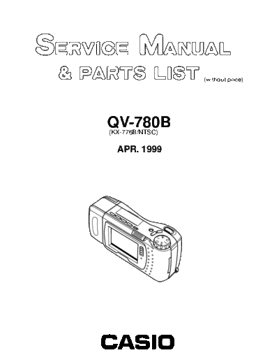
QV-780B
(KX-776B/NTSC)
APR. 1999
INDEX
R
CONTENTS
SPECIFICATIONS ......................................................................................................................................1
WIRING AND BLOCK DIAGRAM .............................................................................................................. 3
POWER SUPPLY CIRCUIT OPERATION .................................................................................................. 4
ADJUSTMENT ...........................................................................................................................................5
1. Unit Adjustment ....................................................................................................................................5
1-1. Color parameters loading ............................................................................................................5
1-2. Scratch compensation .................................................................................................................6
1-3. Flash adjustment .......................................................................................................................... 6
1-4. Flash check ................................................................................................................................... 7
1-5. Current consumption ...................................................................................................................8
1-6. Clock reset ....................................................................................................................................8
1-7. Other test modes .......................................................................................................................... 9
2. PCB K772-DA Adjustment ....................................................................................................................9
2-1. VCC1, VCC3 voltage check ........................................................................................................ 10
2-2. VCC7, VEE3 adjustment ............................................................................................................. 10
2-3. Clock oscillation check .............................................................................................................. 10
3. PCB K772-L Adjustment ..................................................................................................................... 11
3-1. VCC1 adjustment and VCC2, VCC6, VEE2, VCC0 voltage check ........................................... 12
3-2. VCO free run frequency adjustment ......................................................................................... 12
3-3. Backlight drive voltage adjustment .......................................................................................... 12
3-4. VCOM AC adjustment and VCOM DC coarse adjustment....................................................... 13
3-5. Brightness voltage setting and contrast adjustment .............................................................. 13
3-6. Color adjustment ........................................................................................................................ 14
3-7. TINT adjustment .......................................................................................................................... 14
3-8. VCOM DC adjustment .................................................................................................................15
DISASSEMBLY ........................................................................................................................................ 16
PRINTED CIRCUIT BOARDS ..................................................................................................................22
TROUBLESHOOTING ............................................................................................................................. 26
EXPLODED VIEW ....................................................................................................................................28
PARTS LIST ............................................................................................................................................. 30
SCHEMETIC DIAGRAMS ........................................................................................................................ 36
SPECIFICATIONS
Item Specification
Recording System Digital (JPEG base); PC Link software can be used to input images in CAM,
JPEG, TIFF and other format.
Recording Medium Memory card (2MB card included)
Memory Capacity FINE: 14 images (Minimum) (133KB compressed)
(2MB Card)/ NORMAL: 26 images (Minimum) (70KB compressed)
Computer Output image ECONOMY: 47 images (Minimum) (38KB compressed)
The above figures are approximations only. The actual number of images
depends on image subject matter.
Image Element 1/4-inch CCD (350,000 pixels)
Computer Output image 640 x 480 pixels
Lens Fixed focal point with macro position; F2, f = 3.94mm
Aperture F2, F8 switching/fixed
Focus Range NORMAL: 0.7m to
MACRO: 14cm to 16cm (From surface of protective lens.)
Light Metering TTL center priority by CCD
Exposure Metering Program AE
Exposure Range EV +5 to 18
Exposure Correction ◦ Jabse Service Manual Search 2026 ◦ Jabse Pravopis ◦ onTap.bg ◦ Other service manual resources online : Fixya ◦ eServiceinfo