Service Manuals, User Guides, Schematic Diagrams or docs for : DENON AM FM Stereo Receiver AM FM Stereo Receiver Denon - DRA-700AE & DRA-700AEDAB & DRA-500AE Схема 2 DRA-700AE & DRA-700AEDAB & DRA-500AE

<< Back | Home

Most service manuals and schematics are PDF files, so You will need Adobre Acrobat Reader to view : Acrobat Download Some of the files are DjVu format. Readers and resources available here : DjVu Resources
For the compressed files, most common are zip and rar. Please, extract files with Your favorite compression software ( WinZip, WinRAR ... ) before viewing. If a document has multiple parts, You should download all, before extracting.
Good luck. Repair on Your own risk. Make sure You know what You are doing.


Image preview - the first page of the document
Схема 2 DRA-700AE & DRA-700AEDAB & DRA-500AE


>> Download Схема 2 DRA-700AE & DRA-700AEDAB & DRA-500AE documenatation <<

Text preview - extract from the document
                                                                          DRA-700AE/700AEDAB/500AE

BLOCK DIAGRAM
                             Downloaded from http://receiverfaq.ru/
  DRA-700AE/700AEDAB model


                                                                      4
                      DRA-700AE/700AEDAB/500AE

DRA-500AE model


                  5
                    DRA-700AE/700AEDAB/500AE


LEVEL DIAGRAM


                6
                                                                         DRA-700AE/700AEDAB/500AE
SCHEMATIC DIAGRAMS (1/7)
   1             2         3   4   5   6   7   8   9     10                        11


                                                                                                A


                                                                                                B


                                                                                                C


                                                                                                D


                                                                                                E


                                                                                                F


                                                                                                G


                                                                    SIGNAL LINE


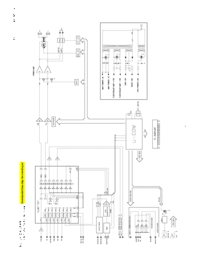
                                                       SCHEMATIC DIAGRAMS (1/7)                 H
                                                       INPUT UNIT
                                                       (for ALL model)
                                                                         DRA-700AE/700AEDAB/500AE
SCHEMATIC DIAGRAMS (2/7)
   1             2         3   4   5   6   7   8   9     10                        11


                                                                                                A


                                                                                                B


                                                                                                C


                                                                                                D


                                                                                                E


                                                                                                F


                                                                                                G


                                                       SCHEMATIC DIAGRAMS (2/7)                 H
                                                       CPU/CNT UNIT
                                                       (for ALL model)
                                                                     DRA-700AE/700AEDAB/500AE
SCHEMATIC DIAGRAMS (3/7)
   1             2         3   4   5   6   7   8   9    10                     11


                                                                                            A


                                                                                            B


                                                                                            C


                                                                                            D


                                                                                            E


                                                                                            F


                                                             POWER S/W B'D


                                                                                            G


                                                                 SIGNAL LINE


                                                       SCHEMATIC DIAGRAMS (3/7)             H
                                                       MAIN/POWER SW UNIT
                                                       (for ALL model)
                                                                        DRA-700AE/700AEDAB/500AE
SCHEMATIC DIAGRAMS (4/7)
   1             2         3   4   5   6     7    8   9    10                     11


                                                                                               A


                                                                                               B


                                                                                               C


                                                                                               D


                                           A
                                           B
                                           C
                                           D
                                           E                                                   E
                                           GND
                                           5.6V


                                                                                               F


                                                                                               G


                                                          SCHEMATIC DIAGRAMS (4/7)             H
                                                          VIDEO UNIT
                                                          FUNCTION SW UNIT
                                                          (for ALL model)
                                                                      DRA-700AE/700AEDAB/500AE
SCHEMATIC DIAGRAMS (5/7)
   1             2         3   4   5   6   7   8   9    10                       11


                                                                                             A


                                                                                             B


                                                                                             C


                                                                                             D


                                                                                             E


                                                                                             F


                                                                                             G


                                                       SCHEMATIC DIAGRAMS (5/7)              H
                                                       FRONT/HEAD PHONE/ZONE UNIT
                                                       (for DRA-700AE/700AEDAB model)
                                                                    DRA-700AE/700AEDAB/500AE
SCHEMATIC DIAGRAMS (6/7)
   1             2         3   4   5   6   7   8   9    10                     11


                                                                                           A


                                                                                           B


                                                                                           C


                                                                                           D


                                                                                           E


                                                                                           F


                                                                                           G


                                                       SCHEMATIC DIAGRAMS (6/7)            H
                                                       FRONT/HEAD PHONE UNIT
                                                       (for DRA-500AE model)
                                                                         DRA-700AE/700AEDAB/500AE
SCHEMATIC DIAGRAMS (7/7)
   1             2         3   4   5   6   7   8   9     10                        11


                                                                                                A


                                                                                                B


                                                                                                C


                                                                                                D


                                                                                                E


                                                                                                F


                                                                                                G


                                                       SCHEMATIC DIAGRAMS (7/7)                 H
                                                       AUDIO UNIT
                                                       (for ALL model)


◦ Jabse Service Manual Search 2024 ◦ Jabse PravopisonTap.bg ◦ Other service manual resources online : FixyaeServiceinfo