Service Manuals, User Guides, Schematic Diagrams or docs for : DENON AV Surround Amplifier & Receiver AV Surround Amplifier & Receiver Denon - AVC-A1D & AVR-5700 Схема AVC-A1D & AVR-5700
<< Back | HomeMost service manuals and schematics are PDF files, so You will need Adobre Acrobat Reader to view : Acrobat Download Some of the files are DjVu format. Readers and resources available here : DjVu Resources
For the compressed files, most common are zip and rar. Please, extract files with Your favorite compression software ( WinZip, WinRAR ... ) before viewing. If a document has multiple parts, You should download all, before extracting.
Good luck. Repair on Your own risk. Make sure You know what You are doing.
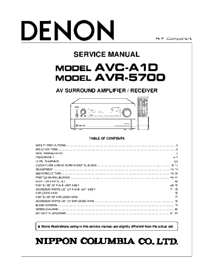
Image preview - the first page of the document

>> Download Схема AVC-A1D & AVR-5700 documenatation <<
Text preview - extract from the document
                                                                                                                                                      Hi-Fi Component


                                               SERVICE MANUAL
                        MODEL                                             AVC-A1D
                        MODEL                                             AVR-5700
                         AV SURROUND AMPLIFIER / RECEIVER


                                                             -- TABLE OF CONTENTS --

SAFETY PRECAUTIONS ...................................................................................................................................................... 2
SPECIFICATIONS ................................................................................................................................................................. 2
WIRE ARRANGEMENT ........................................................................................................................................................ 3
DISASSEMBLY ................................................................................................................................................................ 4~7
LEVEL DIAGRAMS ............................................................................................................................................................ 8,9
CLOCK FLOW & WAVE FORM IN DIGITAL BLOCK .................................................................................................... 10,11
ADJUSTMENT .............................................................................................................................................................. 12~14
SEMICONDUCTORS ................................................................................................................................................... 15~39
PRINTED WIRING BOARDS ....................................................................................................................................... 40~47
NOTE FOR PARTS LIST ..................................................................................................................................................... 48
PARTS LIST OF P.W.B. UNIT ASS'Y .......................................................................................................................... 48~70
ADDENDUM PARTS LIST OF P.W.B. UNIT ASS'Y .................................................................................................... 71~75
EXPLODED VIEW ............................................................................................................................................................... 76
PARTS LIST OF EXPLODED VIEW ................................................................................................................................... 77
ADDENDUM PARTS LIST OF EXPLODED VIEW ............................................................................................................. 78
BLOCK DIAGRAM ............................................................................................................................................................... 79
WIRING DIAGRAM .............................................................................................................................................................. 80
SCHEMATIC DIAGRAMS ............................................................................................................................................ 81~97


  q    Some illustrations using in this service manual are slightly different from the actual set.
AVC-A1D/AVR-5700


        SAFETY PRECAUTIONS
        The following check should be performed for the continued protection of the customer and service technician.


        LEAKAGE CURRENT CHECK
        Before returning the unit to the customer, make sure you make either (1) a leakage current check or (2) a line to chassis
        resistance check. If the leakage current exceeds 0.5 milliamps, or if the resistance from chassis to either side of the
        power cord is less than 460 kohms, the unit is defective.


    SPECIFICATIONS
    Audio Section
    (Power Amplifier)
      Rated output:                           Front:        140 W + 140 W (8 /ohms, 20 Hz ~ 20 kHz with 0.05 % T.H.D.)
                                                            170 W + 170 W (8 /ohms, 1 kHz with 0.7 % T.H.D.)
                                              Surround:     140 W
◦ Jabse Service Manual Search 2024 ◦ Jabse Pravopis ◦ onTap.bg ◦ Other service manual resources online : Fixya ◦ eServiceinfo