Service Manuals, User Guides, Schematic Diagrams or docs for : DENON CD DN-S5000 hfe_denon_dn-s5000_service_en

<< Back | Home

Most service manuals and schematics are PDF files, so You will need Adobre Acrobat Reader to view : Acrobat Download Some of the files are DjVu format. Readers and resources available here : DjVu Resources
For the compressed files, most common are zip and rar. Please, extract files with Your favorite compression software ( WinZip, WinRAR ... ) before viewing. If a document has multiple parts, You should download all, before extracting.
Good luck. Repair on Your own risk. Make sure You know what You are doing.


Image preview - the first page of the document
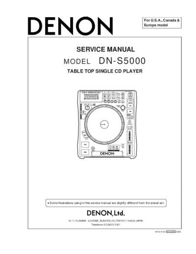
hfe_denon_dn-s5000_service_en


>> Download hfe_denon_dn-s5000_service_en documenatation <<

Text preview - extract from the document
                                                                           For U.S.A., Canada &
                                                                           Europe model


                     SERVICE MANUAL
           MODEL                       DN-S5000
             TABLE TOP SINGLE CD PLAYER


Some illustrations using in this service manual are slightly different from the actual set .


              16-11, YUSHIMA 3-CHOME, BUNKYOU-KU,TOKYO 113-0034 JAPAN
                                Telephone: 03 (3837) 5321

                                                                                    X0161V.02 MO/CDM 0302
                                                                                                        DN-S5000         2

DISASSEMBLY
    (Follow the procedure below in reverse order when reassembling)

1. SLIP DISC, SLIP MAT
     (1)   Remove a screw 69 and pull out Slip Disc and Slip Mat.
.


                                                                     Washer
                                                69
                                                                          Slip Disc


                                                                          Slip Mat

                                                                                        Slip Sheet


                                                                                                     Anti-static Sheet


2. PLATTER
     (1)   Remove Belt from Motor Pully.
     (2)   Remove 3 screws 60 and pull out Platter.
.


                                                                60             60
                                                                                      Platter
                                             Belt


                             Motor Pully


                                                               2
                                                                                                          DN-S5000   3
3. DRIVE UNIT
        (1)     Remove 4 screws 71 and pull out Drive Unit.
        (2)     Disconnect Flat cable and Connector.
        (3)     Detach Drive Unit.
.


                                          Drive Unit


                                    71

                                                       71


                                  Connector
                                                                                Flat cable
                             Drive Unit


Note:
    Do not pull out aslant to prevent Flat cable damage.
    Do not fail to pull AC cord from wall outlet before disconnect the Flat cable and Connector.
      If AC cord is remained plugged into wall outlet, power is kept supplied in the unit, which may cause danger.

4. COVER UNIT
        (1)     Remove 5 screws 70 and pull out Cover Unit.
        (2)     Disconnect Connectors.
        (3)     Detach Cover unit.
.


                                                                                                      Cover unit     70

                                             CX042             70


        Connector                            CX101


                                   CX041
                                                                                                                         70


    Connector


                                     CX031

Note:
    Do not fail to pull AC cord from wall outlet before disconnect Connectors.
      If AC cord is remained plugged into wall outlet, power is kept supplied in the unit, which may cause danger.


                                                                 3
                                                                                                  DN-S5000   4
5. SENSOR AND SCALE UNITS OF PLATTER
    (1)   Remove 2 screws 64 and pull out Sensor Cover and Sensor unit.
    (2)   Remove a E Ring.
    (3)   Pull out Scale unit.
                                                            64
                                               64
                                                                     E Ring

                                    Sensor Cover
                                                                               Scale unit

                                    Sensor unit


6. SENSOR AND SCALE UNITS OF SLIP DISC
    (1)   Remove 2 screws 64 and pull out Sensor Cover and Sensor unit.
    (2)   Remove a screw 60 and pull out Scale unit.
.


                                           Scale unit        64          64

                                      60                                  Sensor Cover


                                                                                    Sensor unit


7. POWER PWB
    (1)   Remove 5 screw 51 and pull out Power PWB.
.


                                                                51
                                                                              Power PWB
                                                                                            51


                                                            4
                                                                                                 DN-S5000   5
8. DSP PWB UNIT
    (1)   Remove 9 screws 52 and pull out DSP PWB unit
.


                                                                          52


                                    DSP PWB unit


                                                            52
                                                                     52
9. DRIVE COVER
    (1)   Remove 4 screws 12 and pull out Drive cover.
.


                                          19


                                     Drive cover

                        19


                                                                                            19

                                                                                       19


10. DRIVE
    (1)   Move Drive Rack in arrow direction through the Hole on the bottom chassis.
          Loader frame comes out.
    (2)   Pull up Loader panel while pulling it towards front.
    (3)   Remove 4 screws 6 and pull out Drive.
.


                                                Drive


                                                                                            4


                                                                                       6
                                                        6        4


                                                                 5
                                                                                                                                                                                                                                                         DN-S5000       6


BLOCK DIAGRAM
       1                            2                              3                                       4                                          5                  6                                        7                                        8


   DN-S5000
                                                                                                                                                                                                                           -HB,F1,F2
                                                                                                                                                                                                                           GND,+5,+9                                    A
                                                                                                                                    33M                                                                                                                     LEDdriver
                                                           128Mb                           D16 ~ 31                                                                                                                                                         BU2090
                                                           SDRAM                                                         TFS0                      LRCK                                            main out
                                                                                                                        TCK0                       BCLK                              AMP10
           ROM                                                                             ADRESS     ADSP21065L       TXD0A                       MAIN1         8CH                                                                          PANEL
          DRIVE                                                                                                        TXD0B                       MON1          D/A                               mon out                                    


◦ Jabse Service Manual Search 2026 ◦ Jabse PravopisonTap.bg ◦ Other service manual resources online : FixyaeServiceinfo