Service Manuals, User Guides, Schematic Diagrams or docs for : DENON CD DN-S3500 hfe_denon_dn-s3500_service_en

<< Back | Home

Most service manuals and schematics are PDF files, so You will need Adobre Acrobat Reader to view : Acrobat Download Some of the files are DjVu format. Readers and resources available here : DjVu Resources
For the compressed files, most common are zip and rar. Please, extract files with Your favorite compression software ( WinZip, WinRAR ... ) before viewing. If a document has multiple parts, You should download all, before extracting.
Good luck. Repair on Your own risk. Make sure You know what You are doing.


Image preview - the first page of the document
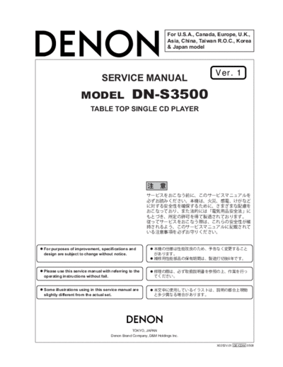
hfe_denon_dn-s3500_service_en


>> Download hfe_denon_dn-s3500_service_en documenatation <<

Text preview - extract from the document
                                                                    For U.S.A., Canada, Europe, U.K.,
                                                                    Asia, China, Taiwan R.O.C., Korea
                                                                    & Japan model


                                                                                      Ver. 1
                               SERVICE MANUAL
                    MODEL                      DN-S3500
                         TABLE TOP SINGLE CD PLAYER


For purposes of improvement, specifications and
design are subject to change without notice.


Please use this service manual with referring to the
operating instructions without fail.


Some illustrations using in this service manual are
slightly different from the actual set.


                                               TOKYO, JAPAN
                                    Denon Brand Company, D&M Holdings Inc.

                                                                                       X0252V.01 DE/CDM 0508
                                                                                                                DN-S3500


SAFETY PRECAUTIONS
The following check should be performed for the continued protection of the customer and service technician.

LEAKAGE CURRENT CHECK
Before returning the unit to the customer, make sure you make either (1) a leakage current check or (2) a line to chassis
resistance check. If the leakage current exceeds 0.5 milliamps, or if the resistance from chassis to either side of the
power cord is less than 460 kohms, the unit is defective.

LASER RADIATION
Do not stare into beam or view directly with optical instruments, class 3A laser product.


                                                                          500V


                                                                                             1M


(1)


(2)


                                                                   (1)

                                                                   (2)


                                                             2
                                                                                                                      DN-S3500


DISASSEMBLY
(Follow the procedure below in reverse order when reassembling.)
Note: First of all, remove the Platter. Refer to the Instruction Manuals.

 1. Bottom Plate
  (1) Remove 4 screws 70 and pull out Bottom Plate.

                                                      70


                                                                       Bottom Plate


                                                                       70


 2. Top Cover unit
  (1) Remove 4 screws 71.
  (2) Detach FFC ESC.
  (3) Remove 2 Push Rivets 31.
  (4) Disconnect Connector to remove Eject LED unit.
  (5) Remove 6 screws 71.
  (6) Disconnect FFC Cable and Connector.
  (7) Detach Top Cover unit.


                                                             71
                                                           Front ESC

                                                                              71
                                                                                      Connector
                                                                                        CW121
                                71                                71


          Connector
            CX032


                           31
                                                                  71                                             FFC Cable
                                                                                                                   CX251
                        Eject LED unit

    Note:
       Do not pull out aslant to prevent FFC cable damage.
       Do not fail to pull AC cord from wall outlet before disconnect FFC Cable.
       If AC cord is remained plugged into wall outlet, power is kept supplied in the unit, which may cause danger.

                                                                       3
                                                                                                                   DN-S3500

3. Motor unit
(1) Remove 4 screws 74.
(2) Detach Motor unit (FG3500).


                                                                        Motor unit
                                              74                           (FG3500)

                                                                       74


4. Mecha unit
(1) Remove 2 screws 63 and 2 screws 64.
(2) Disconnect FFC cable and Connector.
(3) Detach Mecha Unit.


                                            Connector
                                              CX061
                                                                               64

                                                                                                     63


                                                                                 63


                                                        FFC Cable
                                                          CX361
   Mecha unit


 Note:
    Do not pull out aslant to prevent FFC cable damage.
    Do not fail to pull AC cord from wall outlet before disconnect FFC cable.
    If AC cord is remained plugged into wall outlet, power is kept supplied in the unit, which may cause danger.


                                                            4
                                                                                                              DN-S3500

5. Power P.W.B.
(1) Remove 6 screws 69, a screws 72 and a screws 73.
(2) Detach Power P.W.B.


                                                                    Power P.W.B.
                                                    69
                                                                            73

                                                                                   72

                                                          69                            69


                                                                            69


6. Main P.W.B.
(1) Short-circuit the short land above.
(2) Remove a screws 65 and a screws 66.
(3) Disconnect FFC Cable and FPC Cable.
(4) Detach Main P.W.B.


                                                                                             65


                                          Main P.W.B.                                             FPC Cable


                                                               66


               Short land for laser diode


                                                               FFC Cable


 Note:
    Do not pull out aslant to prevent FFC cable damage.


                                                               5
                                                                                     DN-S3500

7. Shield Plate (E3 Model only)
(1) Remove 4 screws 60.
(2) Detach Shield Plate.


                                                                 Shield Plate


                                                        60
                                            60


8. CD Mecha
(1) Remove 2 screws 63 and pull out Main Pwb Bracket.
(2) Remove 2 screws 64 and pull out Disc Guide.


                                              Main Pwb Bracket
                                                                        63
                                                                                63
                                     CD Mecha


                           Disc Guide


                                64


                                             64


                                                        6
                    DN-S3500


BLOCK DIAGRAM


                7
                                                                                                                                                DN-S3500


CONFIRMING THE SERVO
What is Service Program
Service program is a special program intended for confirming servo functions etc.
Required Measuring Implement
Reference disc (TCD784 or CO-74176)
1. Contents of Service Program
Turn on the power while pressing both B button and the PARAMETER knob to set the service mode of DN-S3500. The various
check items can be selected with the PARAMETER knob, the various test items can be selected with the A, SAMP, EXIT/RELOOP,
(SAMP.)EXIT/RELOOP,             and BEND buttons. Press either the PARAMETER knob or PLAY/PAUSE button to start the check
or test and display the result.
To eject the disc, press the DISC EJECT button.
To cancel the service mode, turn the power off.

              Process No.         Function
                (TRACK                                                                   Contents
                             (Character-display)
              Indication)
                                                    A PARAMETER knob is pushed and a version is checked.


◦ Jabse Service Manual Search 2026 ◦ Jabse PravopisonTap.bg ◦ Other service manual resources online : FixyaeServiceinfo