Service Manuals, User Guides, Schematic Diagrams or docs for : DENON DVD Video Player DVD Video Player Denon - DVD-2500BT & 3800BD Схема DVD-2500BT
<< Back | HomeMost service manuals and schematics are PDF files, so You will need Adobre Acrobat Reader to view : Acrobat Download Some of the files are DjVu format. Readers and resources available here : DjVu Resources
For the compressed files, most common are zip and rar. Please, extract files with Your favorite compression software ( WinZip, WinRAR ... ) before viewing. If a document has multiple parts, You should download all, before extracting.
Good luck. Repair on Your own risk. Make sure You know what You are doing.
Image preview - the first page of the document
>> Download Схема DVD-2500BT documenatation <<
Text preview - extract from the document
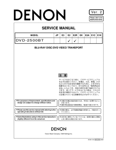
Ver. 2
Please refer to the
MODIFICATION NOTICE.
SERVICE MANUAL
MODEL JP E3 E2 E2R EK E2A E1C E1K
DVD-2500BT
BLU-RAY DISC/DVD VIDEO TRANSPORT
For purposes of improvement, specifications and
design are subject to change without notice.
Please use this service manual with referring to the
operating instructions without fail.
Some illustrations using in this service manual are
slightly different from the actual set.
e
Denon Brand Company, D&M Holdings lnc.
X0393 V.02 DE/CDM 0808
SAFETY PRECAUTIONS
The following check should be performed for the continued protection of the customer and service technician.
LEAKAGE CURRENT CHECK
Before returning the unit to the customer, make sure you make either (1) a leakage current check or (2) a line to chassis
resistance check. If the leakage current exceeds 0.5 milliamps, or if the resistance from chassis to either side of the
power cord is less than 460 kohms, the unit is defective.
LASER RADIATION
Caution - Class 1M visible and invisible laser radiation when open.
Do not view directly with optical instruments.
CAUTION Please heed the points listed below during servicing and inspection.
Heed the cautions! Inspect for safety after servicing!
Spots requiring particular attention when servicing, such Check that all screws, parts and wires removed or discon-
as the cabinet, parts, chassis, etc., have cautions indicated nected for servicing have been put back in their original po-
on labels or seals. Be sure to heed these cautions and the sitions, inspect that no parts around the area that has been
cautions indicated in the handling instructions. serviced have been negatively affected, conduct an insu-
lation check on the external metal connectors and between
Caution concerning electric shock! the blades of the power plug, and otherwise check that
safety is ensured.
(1) An AC voltage is impressed on this set, so touching in-
ternal metal parts when the set is energized could
(Insulation check procedure)
cause electric shock. Take care to avoid electric shock,
Unplug the power cord from the power outlet, disconnect
by for example using an isolating transformer and
the antenna, plugs, etc., and turn the power switch on. Us-
gloves when servicing while the set is energized, un-
ing a 500V insulation resistance tester, check that the in-
plugging the power cord when replacing parts, etc.
sulation resistance between the terminals of the power
(2)There are high voltage parts inside. Handle with extra plug and the externally exposed metal parts (antenna ter-
care when the set is energized. minal, headphones terminal, microphone terminal, input
terminal, etc.) is 1M or greater. If it is less, the set must
be inspected and repaired.
Caution concerning disassembly and
assembly!
Though great care is taken when manufacturing parts from
sheet metal, there may in some rare cases be burrs on the Concerning important safety
edges of parts which could cause injury if fingers are
CAUTION
moved across them. Use gloves to protect your hands.
parts
Many of the electric and structural parts used in the set
Only use designated parts!
have special safety properties. In most cases these prop-
The set's parts have specific safety properties (fire resis- erties are difficult to distinguish by sight, and using re-
tance, voltage resistance, etc.). For replacement parts, be placement parts with higher ratings (rated power and
sure to use parts which have the same properties. In par- withstand voltage) does not necessarily guarantee that
ticular, for the important safety parts that are marked z on safety performance will be preserved. Parts with safety
wiring diagrams and parts lists, be sure to use the desig- properties are indicated as shown below on the wiring dia-
nated parts. grams and parts lists is this service manual. Be sure to re-
place them with parts with the designated part number.
Be sure to mount parts and arrange
the wires as they were originally! (1) Schematic diagrams ... Indicated by the z mark.
For safety reasons, some parts use tape, tubes or other in- (2) Parts lists ... Indicated by the z mark.
sulating materials, and some parts are mounted away from
Using parts other than the designated
the surface of printed circuit boards. Care is also taken with
parts could result in electric shock, fires or
the positions of the wires inside and clamps are used to
other dangerous situations.
keep wires away from heating and high voltage parts, so
be sure to set everything back as it was originally.
2
DVD-2500BT
DIMENSION
3
DVD-2500BT
WIRE ARRANGEMENT
If wire bundles are untied or moved to perform adjustment or parts replacement etc., be sure to rearrange
them neatly as they were originally bundled or placed afterward.
Otherwise, incorrect arrangement can be a cause of noise generation.
Wire arrangement viewed from the top
4
DVD-2500BT
SPECIFICATIONS
5
DVD-2500BT
LASER BEAM SAFETY PRECAUTIONS
This BD player uses a pickup that emits a laser beam.
Do not look directly at the laser beam coming
from the pickup or allow it to strike against your
skin.
The laser beam is emitted from the location shown in the figure. When checking the laser diode, be sure to keep
your eyes at least 30 cm away from the pickup lens when the diode is turned on. Do not look directly at the laser
beam.
CAUTION: Use of controls and adjustments, or doing procedures other than those specified herein, may result in
hazardous radiation exposure.
Drive Mechanism Assembly
Laser Beam Radiation
Laser Pickup
Turntable
Location: Inside Top of BD mechanism.
B1.5 Mechanism Assembly
s
6
DVD-2500BT
LASER BEAM SAFETY PRECAUTIONS s
This BD player uses a pickup that emits a laser beam.
Do not look directly at the laser beam coming
from the pickup or allow it to strike against your
skin.
The laser beam is emitted from the location shown in the figure. When checking the laser diode, be sure to keep
your eyes at least 30 cm away from the pickup lens when the diode is turned on. Do not look directly at the laser
beam.
CAUTION: Use of controls and adjustments, or doing procedures other than those specified herein, may result in
hazardous radiation exposure.
Drive Mechanism Assembly
Laser Beam Radiation
Laser Pickup
Turntable
CAUTION
LASER RADIATION
WHEN OPEN. DO NOT
STARE INTO BEAM.
Location: Top of BD mechanism.
B1.0 Mechanism Assembly
7
DVD-2500BT
Safety Check after Servicing
Examine the area surrounding the repaired location
for damage or deterioration. Observe that screws, Chassis or Secondary Conductor
parts, and wires have been returned to their original
positions. Afterwards, do the following tests and con- Primary Circuit
firm the specified values to verify compliance with
safety standards. d' d
1. Clearance Distance
When replacing primary circuit components, confirm
specified clearance distance (d) and (d') between sol-
dered terminals, and between terminals and surround-
ing metallic parts. (See Fig. 1)
Table 1 : Ratings for selected area
AC Line Voltage Clearance Distance (d), (d')
Fig. 1
3 mm(d)
230 V
6 mm(d')
Note: This table is unofficial and for reference only. Exposed Accessible Part
Be sure to confirm the precise values.
2. Leakage Current Test
Confirm the specified (or lower) leakage current
between B (earth ground, power cord plug prongs) AC Voltmeter
and externally exposed accessible parts (RF termi- Z (High Impedance)
nals, antenna terminals, video and audio input and
output terminals, microphone jacks, earphone jacks,
etc.) is lower than or equal to the specified value in the
table below.
Measuring Method (Power ON) : One side of
B
Insert load Z between B (earth ground, power cord Power Cord Plug Prongs
plug prongs) and exposed accessible parts. Use an
Fig. 2
AC voltmeter to measure across the terminals of load
Z. See Fig. 2 and the following table.
Table 2: Leakage current ratings for selected areas
One side of power cord plug
AC Line Voltage Load Z Leakage Current (i)
prongs (B) to:
2k RES.
i0.7mA AC Peak RF or
Connected in
i2mA DC Antenna terminals
parallel
230 V
50k RES.
i0.7mA AC Peak
Connected in A/V Input, Output
i2mA DC
parallel
Note: This table is unofficial and for reference only. Be sure to confirm the precise values.
8
DVD-2500BT
STANDARD NOTES FOR SERVICING
Circuit Board Indications Pb (Lead) Free Solder
1. The output pin of the 3 pin Regulator ICs is When soldering, be sure to use the Pb free solder.
indicated as shown.
How to Remove / Install Flat Pack-IC
Top View Bottom View
Input 1. Removal
Out In
With Hot-Air Flat Pack-IC Desoldering Machine:
1. Prepare the hot-air flat pack-IC desoldering
2. For other ICs, pin 1 and every fifth pin are machine, then apply hot air to the Flat Pack-IC
indicated as shown. (about 5 to 6 seconds). (Fig. S-1-1)
5
Pin 1
10
3. The 1st pin of every male connector is indicated as
shown.
Fig. S-1-1
Pin 1
2. Remove the flat pack-IC with tweezers while
applying the hot air.
Instructions for Connectors 3. Bottom of the flat pack-IC is fixed with glue to the
1. When you connect or disconnect the FFC (Flexible CBA; when removing entire flat pack-IC, first apply
Foil Connector) cable, be sure to first disconnect soldering iron to center of the flat pack-IC and heat
the AC cord. up. Then remove (glue will be melted). (Fig. S-1-6)
2. FFC (Flexible Foil Connector) cable should be 4. Release the flat pack-IC from the CBA using
inserted parallel into the connector, not at an tweezers. (Fig. S-1-6)
angle. CAUTION:
1. The Flat Pack-IC shape may differ by models. Use
an appropriate hot-air flat pack-IC desoldering
machine, whose shape matches that of the Flat
Pack-IC.
FFC Cable 2. Do not supply hot air to the chip parts around the
flat pack-IC for over 6 seconds because damage
to the chip parts may occur. Put masking tape
Connector around the flat pack-IC to protect other parts from
damage. (Fig. S-1-2)
CBA
* Be careful to avoid a short circuit.
9
DVD-2500BT
3. The flat pack-IC on the CBA is affixed with glue, so With Soldering Iron:
be careful not to break or damage the foil of each 1. Using desoldering braid, remove the solder from
pin or the solder lands under the IC when all pins of the flat pack-IC. When you use solder
removing it. flux which is applied to all pins of the flat pack-IC,
you can remove it easily. (Fig. S-1-3)
Hot-air
Flat Pack-IC Flat Pack-IC Desoldering Braid
Desoldering
Machine
CBA
Soldering Iron
Masking Flat Pack-IC Fig. S-1-3
Tape
Tweezers 2. Lift each lead of the flat pack-IC upward one by
Fig. S-1-2 one, using a sharp pin or wire to which solder will
not adhere (iron wire). When heating the pins, use
a fine tip soldering iron or a hot air desoldering
machine. (Fig. S-1-4)
Sharp
Pin
Fine Tip
Soldering Iron
Fig. S-1-4
3. Bottom of the flat pack-IC is fixed with glue to the
CBA; when removing entire flat pack-IC, first apply
soldering iron to center of the flat pack-IC and heat
up. Then remove (glue will be melted). (Fig. S-1-6)
4. Release the flat pack-IC from the CBA using
tweezers. (Fig. S-1-6)
10
DVD-2500BT
With Iron Wire: 2. Installation
1. Using desoldering braid, remove the solder from 1. Using desoldering braid, remove the solder from
all pins of the flat pack-IC. When you use solder the foil of each pin of the flat pack-IC on the CBA
flux which is applied to all pins of the flat pack-IC, so you can install a replacement flat pack-IC more
you can remove it easily. (Fig. S-1-3) easily.
2. Affix the wire to a workbench or solid mounting 2. The "" mark on the flat pack-IC indicates pin 1.
point, as shown in Fig. S-1-5. (See Fig. S-1-7.) Be sure this mark matches the 1
3. While heating the pins using a fine tip soldering on the PCB when positioning for installation. Then
iron or hot air blower, pull up the wire as the solder presolder the four corners of the flat pack-IC. (See
melts so as to lift the IC leads from the CBA Fig. S-1-8.)
contact pads as shown in Fig. S-1-5. 3. Solder all pins of the flat pack-IC. Be sure that
4. Bottom of the flat pack-IC is fixed with glue to the none of the pins have solder bridges.
CBA; when removing entire flat pack-IC, first apply
soldering iron to center of the flat pack-IC and heat
up. Then remove (glue will be melted). (Fig. S-1-6) Example :
5. Release the flat pack-IC from the CBA using
tweezers. (Fig. S-1-6)
Note: When using a soldering iron, care must be
taken to ensure that the flat pack-IC is not
being held by glue. When the flat pack-IC is
removed from the CBA, handle it gently
because it may be damaged if force is applied.
Pin 1 of the Flat Pack-IC
is indicated by a " " mark.
Hot Air Blower Fig. S-1-7
or
Presolder
Iron Wire
Soldering Iron
To Solid
Mounting Point
Fig. S-1-5
Flat Pack-IC
CBA
Fine Tip Fig. S-1-8
CBA Soldering Iron
Flat Pack-IC
Tweezers
Fig. S-1-6
11
DVD-2500BT
Instructions for Handling Semi-
conductors
Electrostatic breakdown of the semi-conductors may
occur due to a potential difference caused by
electrostatic charge during unpacking or repair work.
1. Ground for Human Body
Be sure to wear a grounding band (1 M) that is
properly grounded to remove any static electricity that
may be charged on the body.
2. Ground for Workbench
Be sure to place a conductive sheet or copper plate
with proper grounding (1 M) on the workbench or
other surface, where the semi-conductors are to be
placed. Because the static electricity charge on
clothing will not escape through the body grounding
band, be careful to avoid contacting semi-conductors
with your clothing.
CBA
Grounding Band
1M
CBA
1M
Conductive Sheet or
Copper Plate
12
DVD-2500BT
CABINET DISASSEMBLY INSTRUCTIONS
1. Disassembly Flowchart 3. NDisassembly Method
This flowchart indicates the disassembly steps to gain
access to item(s) to be serviced. When reassembling, Removal
ID/
follow the steps in reverse order. Bend, route, and Loc. Part Remove/*Unhook/
Fig.
dress the cables as they were originally. No. Unlock/Release/ Note
No.
Unplug/Desolder
[1] Top Cover
[1] Top Cover D1 9(S-1), 2(S-2) ---
[2] Top Panel
[2] Top Panel D2 10(S-3) ---
[3] Tray Panel
[3] Tray Panel D3 *2(L-1) 1
[4] Front Assembly [5] Front CBA
Front 5(S-4), (S-5), *3(L-2),
[4] D3 1
[8] Front Bracket [6] Power SW CBA Assembly *CN2001, *CN4002
[5] Front CBA D4 7(S-6) ---
[9] Rear Panel [7] SD CBA
Power SW
[10] BE Main CBA Unit [6] D4 2(S-7), Desolder ---
CBA
[11] FE Main CBA & BD Mechanism Assembly 2(S-8a), (S-8b), SD
[7] SD CBA D4 PCB Holder, SD Earth ---
[12] Fan Holder Plate
[13] Motor DC Fan Front
[8] D5 2(S-9) ---
Bracket
[14] RS232C CBA [15] Power [17] Sub 2(S-10), 2(S-11),
Supply CBA Microcontroller
[9] Rear Panel D5 2(S-12), (S-13), (S-14), 2
CBA
3(S-15), *CN1003
[16] AV CBA
4(S-16), 4(S-17),
[18] Pedestal 3(S-18), *CN6401,
BE Main *CN7001, *CN7401,
[10] D6 2
2. Disassembly of Main parts CBA Unit BE Scaler Holder, BE
Scaler Sub Holder,
When replacing the main parts, see the following pro- Mecha Earth Plate
cedures. For more details, refer to Fig. D1~D9.
FE Main
Part Steps CBA & BD
[11] D7 4(S-19), *CN2601 3
Mechanism
[10] BE Main CBA Unit [1] [2] *[9](S-14) [10] Assembly
FE Main CBA & BD [1] [2] [3] *[9](S-14) [12] Fan Holder D7 2(S-20), *CN2500 ---
[11] Mechanism [10] [11]
Assembly Motor DC
[13] D7 2(S-21) ---
Fan
[1] [2] *[9](S-14) [10]
[12] Fan Holder [12] RS232C 3(S-22), *CN2551,
[14] D8 ---
[1] [2] *[9](S-14) [10] CBA RS232C Holder
[13] Motor DC Fan [12] [13]
Power 2(S-23), 2(S-24),
[14] RS232C CBA [1] [2] [9] [10] [14] [15] Supply D8 2(S-25), *CN2501, ---
CBA Power PCB Holder
[15] Power Supply CBA [1] [2] *[9](S-14) [12]
[15] [16] AV CBA D8 7(S-26), *CN2503 ---
[1] [2] [3] [9] [10] [11]
[16] AV CBA [12] [13] [14] [16] Sub
[17] Microcontro D9 4(S-27) ---
[17] Sub Microcontroller
CBA [1] [2] [17] ller CBA
[18] Pedestal D9 3(S-28) ---
*About *[9](S-14), remove only (S-14) of Rear Panel.
(1) (2) (3) (4) (5)
13
DVD-2500BT
Note:
(1) Identification (location) No. of parts in the figures
(S-3)
(2) Name of the part [2] Top Panel (S-3)
(3) Figure Number for reference (S-3)
(4) Identification of parts to be removed, unhooked, (S-3)
unlocked, released, unplugged, unclamped, or
desoldered.
P = Spring, L = Locking Tab, S = Screw,
CN = Connector
* = Unhook, Unlock, Release, Unplug, or Desolder
e.g. 2(S-2) = two Screws (S-2),
2(L-2) = two Locking Tabs (L-2)
(5) Refer to "Reference Notes."
About tightening screws
When tightening screws, tighten them with the
following torque.
Torque
0.45 ◦ Jabse Service Manual Search 2026 ◦ Jabse Pravopis ◦ onTap.bg ◦ Other service manual resources online : Fixya ◦ eServiceinfo