Service Manuals, User Guides, Schematic Diagrams or docs for : DENON DVD Video Player DVD Video Player Denon - DVD-2910 & DVD-955 Схема DVD-2910 & DVD-955 Ver. 1
<< Back | HomeMost service manuals and schematics are PDF files, so You will need Adobre Acrobat Reader to view : Acrobat Download Some of the files are DjVu format. Readers and resources available here : DjVu Resources
For the compressed files, most common are zip and rar. Please, extract files with Your favorite compression software ( WinZip, WinRAR ... ) before viewing. If a document has multiple parts, You should download all, before extracting.
Good luck. Repair on Your own risk. Make sure You know what You are doing.
Image preview - the first page of the document
>> Download Схема DVD-2910 & DVD-955 Ver. 1 documenatation <<
Text preview - extract from the document
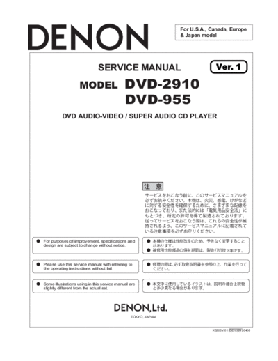
For U.S.A., Canada, Europe
& Japan model
SERVICE MANUAL Ver. 1
MODEL DVD-2910
DVD-955
DVD AUDIO-VIDEO / SUPER AUDIO CD PLAYER
For purposes of improvement, specifications and
design are subject to change without notice.
Please use this service manual with referring to ,
the operating instructions without fail.
Some illustrations using in this service manual are
slightly different from the actual set.
TOKYO, JAPAN
X0203V.01 DE/CDM 0408
DVD-2910/955
SAFETY PRECAUTIONS
LEAKAGE CURRENT CHECK
LASER RADIATION
500V
1M
(1)
(2)
(1)
(2)
2
DVD-2910/955
WIRE ARRANGEMENT
If wire bundles are untied or moved to perform adjustment
or parts replacement etc.,be sure to rearrange them neatly
as they were originally bundled or placed afterward.
Otherwise, incorrect arrangement can be a cause of noise
generation.
Wire arrangement viewed from the top
(Europe model only)
3
DVD-2910/955
DISASSEMBLY
(Follow the procedure below in reverse order when reassem-
bling.)
1. TOP COVER
(1) Remove 4 screws on the both sides, and 2 screws on
the rear.
(2) Widen the Top Cover a little laterally, then detach it with
sliding in the arrow direction.
Top Cover
2. Front Panel, Loader Panel
2.1. When the Disc Tray can be ejected electri-
cally
(1) Plug the power cord to the wall outlet, swicht on the
power, and press the "OPEN/CLOSE" button to open
the Disc Tray.
(2) Detach the Loader Panel by lifting it in the arrow direc-
tion.
(3) Press the "OPEN/CLOSE" buttton to close the Disc
Tray, then unplug the power cord.
(4) Disconnect the wire CX025, CX041, CY171.
(5) Remove 2 top screws and 4 bottom screws, then detach
the Front Panel to the arrow direction.
Front Panel
Power Switch
Loader Panel OPEN/CLOSE bottan
4
DVD-2910/955
2.2. When the Disc Tray cannot be ejected
electrically
(1) Insert a straight ruler etc., into the left side of the Mecha.
Unit and push the A-part (see Fig.) to open the Disc Tray
manually.
(2) Detach the Loader Panel by lifting it in the arrow direc-
tion.
(3) Push the Disc Tray to close it manually.
(4) Dsiconnect the wire CX025, CX041, CY171.
(5) Remove 2 top screws and 4 bottom screws, then detach
the Front Panel to the arrow direction.
A-part
Fig. The left side view of the Mechanism. A straight ruler etc.
A-part A straight ruler etc.
Fig. The left side view of the Mechanism.
3. DVD Mecha
(1) Disconnect the wire CX141, CX174, CX271, CX331.
(2) Remove 4 screws on the DVD Mecha. And 2 screws on
the Main P.W.B., then take it off in the arrow direction.
DVD MECHA
5
DVD-2910/955
4. Mecha. Unit
(1) Remove 2 screws on the top of the Mecha. Unit, and de-
tach the Guide Clamp Bracket with sliding in the arrow
direction.
(2) Solder the short-circuit on the Traverse Unit. (Refer to
"Traverse Unit Disassembly" on page 8.
(3) Disconnect the wires (CX151, CX241, CX051) connect-
ing with the Main P.W.B.
(4) Turn over the Mecha. Unit/Main P.W.B., assembly, and
remove 2 screws.
Guide Clamp Bracket
5. VIDEO P.W.B. & HDMI P.W.B.
(1) Disconnect the wire CY051 (CY051, CY121 : E2 only)
(2) Remove 2 screws on the top side and 10 (Japan 12)
screws on the side., then take it off in the arrow direc-
tion.
VIDEO P.W.B.
HDMI P.W.B.
SCART P.W.B.( E2 only )
6
DVD-2910/955
6. AUDIO P.W.B.
(1) Disconnect the wire CY061 (CX053, CY061 : E2 only)
(2) Remove 6 screws on the top sides and 5 screws on the
rear side., then take it off in the arrow direction.
AUDIO P.W.B.
7. POWER P.W.B. & P.C.B. HOLDER
(1) Disconnect the wire CX024.
(2) Remove 5 screws on the top side and 2 screws on the
side., then take it off in the arrow direction.
(3) P.C.B. HOLDER : take it off in the arrow direction.
P.C.B.HOLDER
POWER P.W.B.
8. REAR PANEL & AC INLET
(1) Remove 3 screws on the bottom side and 2 screws on
the rear side.
(2) AC INLET : Remove 2 screws on the rear side.
REAR PANEL
AC INLET
7
DVD-2910/955
9. FOOT ASS'Y & BOTTOM PLATE
(1) Remove 4 screws on the foot side.
(2) Remove 5 screws on the bottom side.
BOTTOM PLATE
FOOT ASS'Y
10.Traverse Unit Disassembly
Caution: The optical pickup can be damaged easily
by static electricity charged on human body. Take
necessary anti-static measures when repairing
around the optical pickup.
10.1.Guide Clamp Bracket disassembly
(1) Remove 2 screws.
(2) Remove Guide Clamp Bracket to arrow direction.
8
DVD-2910/955
10.2.Tray disassembly
(1) Remove to arrow direction.
(2) Solder the short-circuit (see in the frame).
10.3.Traverse Unit disassembly
(1) Remove 24P FFC (CX241), 15P FFC (CX151), 5P PH
WIRE (CX051) and 3P PH WIRE (CX031) connecting
with from the Main P.W.B.
(2) Remove 4 screws fixing Damper.
(3) Remove Traverse Unit to arrow direction.
9
DVD-2910/955
Note for disassembly Traverse Unit
(1) When assembling, reverse the order of the above.
(2) When inserting Tray, confirm boss on Slide Cam set to
ditch of the Tray (Compare with below drawing).
10
DVD-2910/955
DIAGNOSTICS OF OPTICAL PICKUP
AND REPLACING TRAVERSE UNIT
Make failure diagnostics of the Optical Pickup as follows.
If the laser drive current (Iop) becomes more than 1.5 times of
the initial value, the Optical Pickup should be replaced.
The laser drive current is registered on the seal attached to the
rear of the Mecha.Unit.
In case of replacing the Pickup, change the whole part of the
Traverse Unit.
No mechanical adjustment is necessary after the replace-
ment.
Example: DVD 30mA
CD 30mA
Disc no read,unsteady playback, etc.
Laser drive current (Iop) check
HF wave form check
(Refer to WAVE FORMS)
Present value exceeds the ini-
tial value by 1.5 times
Traverse Unit replacing
(See page 8, 9 for details)
Laser current registering after replacement.
Step: Disc playback
Write the measured value on the seal attached to the
Mecha. Unit
* As to the measuring method, refer to page 13.
11
DVD-2910/955
1. Label Indication of SACD Mechanism.
Laser current consumption value
ex) DVD mA, CD mA
DVD mA, CD mA
2. Note for Handling the Laser Pick-Up
The protection for the damage of laser diode.
If you want to change the optical device unit from any other
units, you must keep the following.
(1) It should be done at the desk already took measures the
static electricity in care of removing the OPU's (Optical
device unit) connector cable.
(2) Workers should be put on the "Earth Band".
(3) It should be done to add the solder to the short land to
prevent the broken Laser diode before removing the 24P
FFC cable.
(4) Don't touch OPU's connector parts carelessly.
3. Replacement of the Laser Pick-up
(Traverse Unit)
Check the Iop (Laser drive current)
If the present Iop (current) value exceeds.+150% of the ini-
tial value, replace the Traverse unit (Laser Pick-up) with a
new one.
4. Iop Measurement Method
When measuring Laser drive current (Iop), playback the
discs (CD,DVD) described below, measure Iop for CD Laser
and DVD Laser by the test point (+5V-A2~ LD (CD), LD
(DVD))on the Main P.W.B.
Test Disc : DVD/DVDT-S01 or commercially available
discs.
: CD/TCD-784 (manufactured by ALMEDIO
INC) or commercially available discs.
12
DVD-2910/955
4.1. DVD Laser current measurement
LD (DVD) LD (DVD)
+5V-A2 +5V-A2
Oscilloscope Oscilloscope
(1) Connect the oscilloscope to +5V-A2 of test point for
GND side and LD (DVD) of test point for signal side.
(2) Playback the multilayer track 1 of the DVD Test Disc.
(3) Measure the voltage between +5V-A2 and LD (DVD),
calculate Iop by the formula as shown below.
Measurement Voltage Value
Iop = ----------------------------------------------------------------------------
-
14 (Resistance value)
4.2. CD Laser current measurement
(1) Connect the oscilloscope to +5V-A2 of test point for
GND side and LD (CD) of test point for signal side.
(2) Playback the track 1 of the CD Test Disc.
(3) Measure the voltage between +5V-A2 and LD (CD), cal-
culate Iop by the formula as shown below.
Measurement Voltage Value
Iop = ----------------------------------------------------------------------------
-
11.75 (Resistance value)
LD(DVD) LD(CD) +5V-A2
Main Unit foil side
13
DVD-2910/955
SERVICE MODE
1. Aging Mode
(1) preparation
(a) Equipment used: Any one of DVD Karaoke Disc (con-
taining more than 10 titles).
(b) Unit setting : No spec other than the following procedure
(Aging mode).
At the tray open status, press the "POWER" button to
turn on the power while pressing the "PLAY" and
"OPEN/CLOSE" buttons for DVD operation simulta-
neously. mark on the FL lights, and the unit is
set to the heat run mode.
(2) procedure
(a) According the above, set to the aging mode.
(b) Set a DVD Karaoke disc to the tray and press the "PLAY"
button once. mark on the FL blinks, and aging
operation(after playback title-1 and title-10 of the disc,
the tray open/close is made automatically, then playback
the title-1 again) starts. This aging operation continues
automatically until it is stopped or it stops caused by an
error. In case of some error in DVD, the following error
messages are displayed on the FL.
No Error contents FL display
1 Bad Disc ERROR 02 1 ERROR 02
2 Focus Error ERROR 04
3 Read Error ERROR 03
4 Tracking Error ERROR 04
5 Tray Error ERROR 05
6 Navigation Pack Read Error ERROR 06
7 Cmmunication Error ERROR 07
2. Initial Setting Mode
(1) Preparation
(a) Equipment used: None
(b) Unit setting: No spec other than the following procedure
(2) Procedure
(a) Initialize the DVD player when ◦ Jabse Service Manual Search 2026 ◦ Jabse Pravopis ◦ onTap.bg ◦ Other service manual resources online : Fixya ◦ eServiceinfo