Service Manuals, User Guides, Schematic Diagrams or docs for : DENON Home Theatre System Home Theatre System Denon - S-302 Схема S-302 Ver. 9
<< Back | HomeMost service manuals and schematics are PDF files, so You will need Adobre Acrobat Reader to view : Acrobat Download Some of the files are DjVu format. Readers and resources available here : DjVu Resources
For the compressed files, most common are zip and rar. Please, extract files with Your favorite compression software ( WinZip, WinRAR ... ) before viewing. If a document has multiple parts, You should download all, before extracting.
Good luck. Repair on Your own risk. Make sure You know what You are doing.
Image preview - the first page of the document
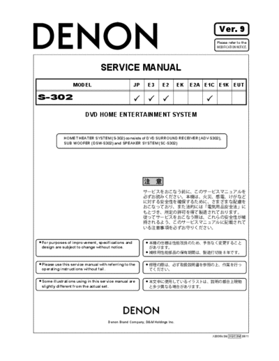
>> Download Схема S-302 Ver. 9 documenatation <<
Text preview - extract from the document
Ver. 9
Please refer to the
MODIFICATION NOTICE.
SERVICE MANUAL
MODEL JP E3 E2 EK E2A E1C E1K EUT
S-302
DVD HOME ENTERTAINMENT SYSTEM
HOME THEATER SYSTEM (S-302) consists of DVD SURROUND RECEIVER (ADV-S302),
SUB WOOFER (DSW-S302) and SPEAKER SYSTEM (SC-S302)
For purposes of improvement, specifications and
design are subject to change without notice.
Please use this service manual with referring to the
operating instructions without fail.
Some illustrations using in this service manual are
slightly different from the actual set.
e
Denon Brand Company, D&M Holdings lnc.
X0335V.09 DE/CDM 0811
SAFETY PRECAUTIONS
The following check should be performed for the continued protection of the customer and service technician.
LEAKAGE CURRENT CHECK
Before returning the unit to the customer, make sure you make either (1) a leakage current check or (2) a line to chassis
resistance check. If the leakage current exceeds 0.5 milliamps, or if the resistance from chassis to either side of the
power cord is less than 460 kohms, the unit is defective.
LASER RADIATION
Do not stare into beam or view directly with optical instruments, class 3A laser product.
CAUTION Please heed the points listed below during servicing and inspection.
Heed the cautions! Inspect for safety after servicing!
Spots requiring particular attention when servicing, such Check that all screws, parts and wires removed or discon-
as the cabinet, parts, chassis, etc., have cautions indicated nected for servicing have been put back in their original po-
on labels or seals. Be sure to heed these cautions and the sitions, inspect that no parts around the area that has been
cautions indicated in the handling instructions. serviced have been negatively affected, conduct an insu-
lation check on the external metal connectors and between
Caution concerning electric shock! the blades of the power plug, and otherwise check that
safety is ensured.
(1) An AC voltage is impressed on this set, so touching in-
ternal metal parts when the set is energized could
(Insulation check procedure)
cause electric shock. Take care to avoid electric shock,
Unplug the power cord from the power outlet, disconnect
by for example using an isolating transformer and
the antenna, plugs, etc., and turn the power switch on. Us-
gloves when servicing while the set is energized, un-
ing a 500V insulation resistance tester, check that the in-
plugging the power cord when replacing parts, etc.
sulation resistance between the terminals of the power
(2)There are high voltage parts inside. Handle with extra plug and the externally exposed metal parts (antenna ter-
care when the set is energized. minal, headphones terminal, microphone terminal, input
terminal, etc.) is 1M or greater. If it is less, the set must
Caution concerning disassembly and be inspected and repaired.
assembly!
Though great care is taken when manufacturing parts from
sheet metal, there may in some rare cases be burrs on the
CAUTION Concerning important safety
edges of parts which could cause injury if fingers are
moved across them. Use gloves to protect your hands.
parts
Only use designated parts! Many of the electric and structural parts used in the set
have special safety properties. In most cases these prop-
The set's parts have specific safety properties (fire resis- erties are difficult to distinguish by sight, and using re-
tance, voltage resistance, etc.). For replacement parts, be placement parts with higher ratings (rated power and
sure to use parts which have the same properties. In par- withstand voltage) does not necessarily guarantee that
ticular, for the important safety parts that are marked z on safety performance will be preserved. Parts with safety
wiring diagrams and parts lists, be sure to use the desig- properties are indicated as shown below on the wiring dia-
nated parts. grams and parts lists is this service manual. Be sure to re-
place them with parts with the designated part number.
Be sure to mount parts and arrange
the wires as they were originally! (1) Schematic diagrams ... Indicated by the z mark.
For safety reasons, some parts use tape, tubes or other in- (2) Parts lists ... Indicated by the z mark.
sulating materials, and some parts are mounted away from
Using parts other than the designated
the surface of printed circuit boards. Care is also taken with
parts could result in electric shock, fires or
the positions of the wires inside and clamps are used to
other dangerous situations.
keep wires away from heating and high voltage parts, so
be sure to set everything back as it was originally.
2
S-302
z
z
z
3
S-302
DIMENSION
ADV-S302
4
S-302
DSW-S302
5
S-302
SC-S302
76.3
60
335
167.5
133
6
S-302
WIRE ARRANGEMENT
If wire bundles are untied or moved to perform adjustment or
parts replacement etc., be sure to rearrange them neatly as
they were originally bundled or placed afterward.
Otherwise, incorrect arrangement can be a cause of noise
generation.
1. ADV-S302
Fasten the CX31 3P connector cord to the circuit board
with a style pin.
Fasten the CX33 3P connector cord and CY072 7P con-
nector cord to the circuit board with a style pin and clamp
band.
Pass the CY211 FFC through the protect sheet.
Pass the CW052 5P connector cord through the protect
sheet.
Fasten the CW051 5P connector cord and CW052 5P
connector cord to the circuit board with a cord holder
CX031
CY211
CY072 Protect Sheet
CY033
CW052 CW051
CX171
7
S-302
Pass the antenna cable next to the CX154 FFC.
Fasten the CW051 5P connector cord and CW052 5P
connector cord with a cord holder.
Anntena Cable
CX154
CW052
CW051
Fasten the CX061 6P connector cord with a cord holder.
CX061
Ferrite Cramp
8
S-302
2. DSW-302 2. DSW-302
Fasten the CX041 4P connector cord to the chassis with
a clamp band.
Fasten the CW041 4P connector cord and CX081 8P
connector cord to the chassis with a clamp band.
Fasten with a clamp band.
Fasten the CX021 2P connector cord to the chassis with
a clamp band.
CX021
CX151
CX041 CX081
CX022
9
S-302
DISASSEMBLY
(Follow the procedure below in reverse order when reassem-
bling.)
ADV-S302
1. Side panel
(1) Remove 4 screws 104 on the rear side and 4 screws
104 on the bottom side.
(2) Detach the Side panel.
104 104
Side panel
104
Side panel
104
2. Top cover
(1) Remove 3 screws 104 on the rear side and 6 screws
105 on the both sides.
(2) Detach the Top cover.
Top cover
105
104
105
104
10
S-302
3. Drive unit
3.1. When the Disc tray can be ejected electrical-
ly.
(1) Switch on, and press [ (OPEN/CLOSE)] button to
open the Disc tray.
(2) Detach the Loader panel by lifting.
(3) Close the Disc tray.
(4) Remove 4 screws 102 on the top side.
(5) Disconnect the Wire [CX061] from the Main unit and
the FFC cable [CY301] from the Drive unit.
(6) Detach the Drive unit
3.2. When the Disc tray cannot be ejected
electrically.
(1) Push the Plate Gear of the Drive unit from direction of
arrow A, to open the Disc Tray.
(2) The same steps described on 3.1. (2)~(6).
Loader panel
102
102
Drive unit
FFC Cable
Wire
A
11
S-302
4. Front panel assy
(1) Remove 3 screws 106 on the bottom side.
(2) Disconnect the Wire [CX051],[CX052] and the FFC
cable [CX211] from the Main unit and the Wire
[CX054] from the USB unit.
(3) Remove 3 screws 103 and 2 screws 105 on the top
side and 2 screws 105 on the both sides.
(4) Detach the Front panel assy.
106
Front panel assy
103
105
105
Wire Wire
FFC Cable
105
103
Front panel assy
105
12
S-302
5. Rear panel assy
(1) Remove 10 screws 103 on the top side.
(2) Remove 5 screws 105 on the rear side and 4 screws
105 on the both sides.
(3) Detach the Rear panel assy.
Rear panel assy
103
103
103
103 103
105
Rear panel assy
105
105
105
13
S-302
DSW-S302
1. Rear panel
(1) Remove 10 screws 101 on the bottom side.
(2) Detach the Rear panel.
101
2. SHIELD COVER
(1) Remove 8 screws 103 on the Side.
(2) Lift the shield cover using a flat-headed screwdriver
and remove it. When doing this, be careful not to de-
form the main bracket's hook.
103
103
103
14
S-302
ATTACHING THE ANTI-SLIP PADS
Attach the anti-slip pads as shown on the diagram be-
low. Press firmly so they do not peel off subsequently.
Speaker stand
2mm
2mm
Wall bracket
3mm
3mm
15
S-302
DIAGNOSTICS OF OPTICAL PICKUP
AND REPLACING TRAVERSE UNIT
Make failure diagnostics of the Optical Pickup as follows.
If the laser drive current (Iop) becomes more than 1.5 times
of the initial value, the Optical Pickup should be replaced.
The laser drive current initial value is checked by "Iop
checked Method" of next page.
In case of replacing the Pickup, change the whole part of
the Traverse Unit.
No mechanical adjustment is necessary after the replace-
ment.
Laser drive current initial value:
DVD:
CD:
Disc no read, unsteady playback, etc.
Laser drive current (Iop) check
HF wave form check
(Refer to WAVE FORMS)
Present value exceeds the ini-
tial value by 1.5 times
Traverse Unit replacing
Laser current (Iop) memorizing after replacement
16
S-302
1. Iop checked Method
Select the laser ON/OFF (CD/DVD) mode of the test
mode, and check the lop value of DVD laser or CD laser.
(See page 21 for test mode.)
1.1. DVD laser current check
(1) Press the SKIP or button to display the
laser current value, and then select T22.
(2) Press the PLAY button and check the current value of
Iop (nnnn).
(Use the disc TDV-520) d
d
( : Off, DVD laser, Initial value: mm.mm [mA],
Current value: nn.nn [mA])
1.2. CD Laser current check
(1) Press the or button to display the laser
current value, and then select T21.
(2) Press the PLAY button and check the current value of
Iop (nnnn).
(Use the disc TCD-784) d
d
( : Off, CD laser, Initial value: mm.mm [mA],
Current value: nn.nn [mA])
2. Note for Handling the Laser Pick-Up
The protection for the damage of laser diode.
If you want to change the optical device unit from any oth-
er units, you must keep the following.
(1) It should be done at the desk already took measures
the static electricity in care of removing the OPU's
(Optical device unit) connector cable.
(2) Workers should be put on the "Earth Band".
(3) It should be done to add the solder to the short land
to prevent the broken Laser diode before removing
the 24P FFC cable.
(4) Don't touch OPU's connector parts carelessly.
3. Replacement of the Laser Pick-up
(Traverse Unit)
Check the Iop (Laser drive current)
If the present Iop (current) value exceeds.+150% of the
initial value, replace the Traverse unit (Laser Pick-up)
with a new one.
17
S-302
4. Rewriting the default value of the laser
current
To rewrite the default value of the laser current, press the
button for at least 5 seconds while the CD or DVD la-
ser current is displayed, then press the or
button to select T23. (For details, see "Iop checked Meth-
od" on page 22.)
If the button is pressed while T23 is displayed, the
current value is displayed at "mmmm" and stored in the
EEPROM.
5. Resetting the accumulated laser on
time
To clear the accumulated laser on time, press the
button while the accumulated laser on time is displayed
(TB1, TB2 : For details, see "Test Mode" on page 22.) un-
til " " appears at the fourth position, then press the
or button to select TB3.
If the button is pressed while TB3 is displayed, the
accumulated laser on time of CD and DVD is cleared.
When TB1 or TB2 is selected with the or
button, "nnnnnnn" is displayed as 0 so you can check.
( : Off, Y 1: CD, 2: DVD, nnnnnnn: Hour [h])
18
S-302
HOW TO REPLACE TRAVERSE
UNIT
Caution: The optical pickup can be damaged easily
by static electricity charged on human
body.
Take necessary anti-static measures when
repairing around the optical pickup.
1. Guide Clamp Bracket disassembly
(1) Remove 2 screws.
(2) Remove Guide Clamp Bracket to arrow direction.
2. Tray disassembly
(1) Remove to arrow direction.
(2) Solder the short-circuit (see in the frame).
Solder to short-circuit
Short-circuit with Solder
19
S-302
3. Traverse Unit disassembly
(1) Remove 24P FFC, 15P FFC and 5P PH WIRE con-
necting with from the Main P.W.B.
(2) Remove 4 screws fixing Damper.
(3) Remove Traverse Unit to arrow direction.
Note for disassembly Traverse Unit
(1) When assembling, reverse the order of the above.
(2) When inserting Tray, confirm boss on Slide Cam set to
ditch of the Tray (Compare with below drawing).
20
S-302
SERVICE MODE
1. Aging Mode
1.1. preparation0
(1) Equipment used: Any one of DVD Karaoke Disc (containing more than 10 titles).
(ex : Heat run disc TDV-HR01)
(2) Unit setting : No spec other than the following procedure.
1.2. procedure
Perform aging of the DVD.
(1) Pressing the and buttons simultaneously, plug the AC cord into a power outlet. This sets the aging mode.
◦ Jabse Service Manual Search 2026 ◦ Jabse Pravopis ◦ onTap.bg ◦ Other service manual resources online : Fixya ◦ eServiceinfo