Service Manuals, User Guides, Schematic Diagrams or docs for : DENON LP Turntable LP Turntable Denon - DP-300F Схема DP-300F Ver. 3
<< Back | HomeMost service manuals and schematics are PDF files, so You will need Adobre Acrobat Reader to view : Acrobat Download Some of the files are DjVu format. Readers and resources available here : DjVu Resources
For the compressed files, most common are zip and rar. Please, extract files with Your favorite compression software ( WinZip, WinRAR ... ) before viewing. If a document has multiple parts, You should download all, before extracting.
Good luck. Repair on Your own risk. Make sure You know what You are doing.
Image preview - the first page of the document
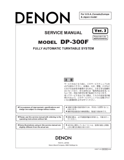
>> Download Схема DP-300F Ver. 3 documenatation <<
Text preview - extract from the document
                                                                             For U.S.A.,Canada,Europe
                                                                             & Japan model


                                                                                         Ver. 3
                               SERVICE MANUAL
                                                                                        Please refer to the
                                                                                        MODIFICATION NOTICE.

                       MODEL                       DP-300F
                FULLY AUTOMATIC TURNTABLE SYSTEM


For purposes of improvement, specifications and
design are subject to change without notice.


Please use this service manual with referring to the
operating instructions without fail.


Some illustrations using in this service manual are
slightly different from the actual set.


                                               TOKYO, JAPAN
                                    Denon Brand Company, D&M Holdings Inc.

                                                                                         X0267 V.03 DE/CDM 0609
                                                                                                                                           DP-300F


  SAFETY PRECAUTIONS
  The following check should be performed for the continued protection of the customer and service technician.

  LEAKAGE CURRENT CHECK
  Before returning the unit to the customer, make sure you make either (1) a leakage current check or (2) a line to chassis
  resistance check. If the leakage current exceeds 0.5 milliamps, or if the resistance from chassis to either side of the power
  cord is less than 460 kohms, the unit is defective.


 CAUTION           Please heed the points listed below during servicing and inspection.

   Heed the cautions!                                                  Inspect for safety after servicing!
Spots requiring particular attention when servicing, such as        Check that all screws, parts and wires removed or discon-
the cabinet, parts, chassis, etc., have cautions indicated on       nected for servicing have been put back in their original posi-
labels or seals. Be sure to heed these cautions and the cau-        tions, inspect that no parts around the area that has been
tions indicated in the handling instructions.                       serviced have been negatively affected, conduct an insulation
                                                                    check on the external metal connectors and between the
   Caution concerning electric shock!                               blades of the power plug, and otherwise check that safety is
                                                                    ensured.
(1) An AC voltage is impressed on this set, so touching inter-
    nal metal parts when the set is energized could cause
                                                                    (Insulation check procedure)
    electric shock. Take care to avoid electric shock, by for ex-
                                                                    Unplug the power cord from the power outlet, disconnect the
    ample using an isolating transformer and gloves when
                                                                    antenna, plugs, etc., and turn the power switch on. Using a
    servicing while the set is energized, unplugging the power
                                                                    500V insulation resistance tester, check that the insulation re-
    cord when replacing parts, etc.
                                                                    sistance between the terminals of the power plug and the ex-
(2)There are high voltage parts inside. Handle with extra care      ternally exposed metal parts (antenna terminal, headphones
    when the set is energized.                                      terminal, microphone terminal, input terminal, etc.) is 1M or
                                                                    greater. If it is less, the set must be inspected and repaired.
   Caution concerning disassembly and assembly!
Though great care is taken when manufacturing parts from
sheet metal, there may in some rare cases be burrs on the
edges of parts which could cause injury if fingers are moved         CAUTION          Concerning important safety parts
across them. Use gloves to protect your hands.
                                                                    Many of the electric and structural parts used in the set have
   Only use designated parts!                                       special safety properties. In most cases these properties are
                                                                    difficult to distinguish by sight, and using replacement parts
The set's parts have specific safety properties (fire resis-        with higher ratings (rated power and withstand voltage) does
tance, voltage resistance, etc.). For replacement parts, be         not necessarily guarantee that safety performance will be pre-
sure to use parts which have the same properties. In particu-       served. Parts with safety properties are indicated as shown
lar, for the important safety parts that are marked ! on wiring     below on the wiring diagrams and parts lists is this service
diagrams and parts lists, be sure to use the designated parts.      manual. Be sure to replace them with parts with the designat-
                                                                    ed part number.
   Be sure to mount parts and arrange the
   wires as they were originally!                                   (1) Schematic diagrams ... Indicated by the ! mark.
For safety reasons, some parts use tape, tubes or other insu-       (2) Parts lists ... Indicated by the ! mark.
lating materials, and some parts are mounted away from the
                                                                                     Using parts other than the designated parts
surface of printed circuit boards. Care is also taken with the
                                                                                     could result in electric shock, fires or other
positions of the wires inside and clamps are used to keep
                                                                                     dangerous situations.
wires away from heating and high voltage parts, so be sure to
set everything back as it was originally.


                                                                                                                                       2
                                                                                 DP-300F

METHOD OF ADJUSTMENT

1. RELATIONSHIP BETWEEN BELT AND
   PULLEY.
  Check that the belt is not touching the collars (A) of the
  motor pulley. If it is, remove the turntable and reattach
  the belt at the center of the turntable skirt.


                               Motor pulley


       Should not touch                         Belt
       here (A)


2. SPEED ADJUSTMENT
  If the speed is off, adjust it with the variable resistor on
  the motor control board.
  Adjust for 33 rpm first, then set at 45 rpm and check.
  After adjusting, check the two speeds (33 and 45 rpm)
  once again.


          This diagram shows the bottom panel.


                                   Foot


                           Adj. Hole for 33 rpm                        33 rpm
                         33 Adj. Hole for 45 rpm                     33 45 rpm
                          45                                          45


                     Motor


                                                                 3
                                                                DP-300F

3. LEAD IN AND LEAD OUT ADJUSTMENT
 (1) Lead in
     (Test record: Hitachi HT-5 (30cm))
  Check that the stylus lowers at 5 to 25 counts for both
  17cm and 30cm records.
 (2) Lead out
     (Test record: Nippon Columbia EM-1001
     (17cm))
  Check that the pickup returns at 3 to 15 counts (3mm
  pitch).

  If the counts are off , adjust as follows:
  (a) Fasten the pickup to the arm rest.
  (b) Detach the Bottom board.
  (c) Insert a screwdriver into the lead in or lead out
      adjustment parts and adjust.
  (d) After adjustment, fix it in Three Bond 1401B.
  (e) Fix the Bottom board.
  Lead in
◦ Jabse Service Manual Search 2026 ◦ Jabse Pravopis ◦ onTap.bg ◦ Other service manual resources online : Fixya ◦ eServiceinfo