Service Manuals, User Guides, Schematic Diagrams or docs for : DENON Stereo Cassette Tape Deck Stereo Cassette Tape Deck Denon - DRR-M31 Схема DRR-M31
<< Back | HomeMost service manuals and schematics are PDF files, so You will need Adobre Acrobat Reader to view : Acrobat Download Some of the files are DjVu format. Readers and resources available here : DjVu Resources
For the compressed files, most common are zip and rar. Please, extract files with Your favorite compression software ( WinZip, WinRAR ... ) before viewing. If a document has multiple parts, You should download all, before extracting.
Good luck. Repair on Your own risk. Make sure You know what You are doing.
Image preview - the first page of the document
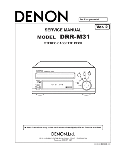
>> Download Схема DRR-M31 documenatation <<
Text preview - extract from the document
                                                                For Europe model


                      SERVICE MANUAL
             MODEL                      DRR-M31
                     STEREO CASSETTE DECK


Some illustrations using in this service manual are slightly different from the actual set.


               16-11, YUSHIMA 3-CHOME, BUNKYOU-KU, TOKYO 113-0034 JAPAN
                                 Telephone: 03 (3837) 5321

                                                                                  X0166V.02 DE/CDM 0302
                                                                                                          DRR-M31           2


SAFETY PRECAUTIONS
The following check should be performed for the continued protection of the customer and service technician.

LEAKAGE CURRENT CHECK
Before returning the unit to the customer, make sure you make either (1) a leakage current check or (2) a line to chassis
resistance check. If the leakage current exceeds 0.5 milliamps, or if the resistance from chassis to either side of the
power cord is less than 460 kohms, the unit is defective.


                                                           2
                                                                    DRR-M31   3

DISASSEMBLY
  (Follow the procedure below in reverse order when reassembling)

1. TOP COVER
   (1)   Remove 2 screws       fixing from the both
         sides.
   (2)   Remove 5 screws fixing to the Rear Plate,
         then detach the Top Cover in the arrow di-
         rection .


2. FRONT PANEL
   (1)   Disconnect 1 HCU joiner coming from the
         front P.W.B.
   (2)   Remove 4 screws    fixing the Front Panel at
         the bottom.
   (3)   Whil releasing 2 hooks, detach the Front
         Panel.


3. CASSETTE MECHA. ASS'Y
   (1)   Remove 4 screws      fixing the Cassette
         Mecha. Ass'y.
   (2)   Disconnect 3 connectors, then detach the
         Cassette Mecha. Ass'y.


                                                          3
                                                                     DRR-M31         4
4. REAR PLATE
    (1)   Pull up the Power Cord together with the cord
          bush to disengage from the Rear Plate.
    (2)   Remove 3 screws       fixing the 4P pin jack and
          AC outlet respectively.
    (3)   Remove 1 screw      , and detach the Rear Plate.


5. MAIN P.W.B.
    (1)   Remove 1 screw       fixing the AMP P.W.B.
    (2)   Pull up the AMP P.W.B. as shown in the arrow
          direction, and disconnect 2 connectors.
                                                                 Connector
    (3)   Remove 4 screws      fixing the Main P.W.B.
    (4)   Release 3 pieces of P.W.B. spacers.
    (5)   Disconnect the connector from the Trans Unit.
    (6)   Take off the Main P.W.B.


                                                                               AMP


6. DISPLAY P.W.B.
    (1)   Pull out the knob (E).
    (2)   Remove the nut and washer         for the rotary
          switch.
    (3)   Remove 9 screws       .
    (4)   Take off the Display P.W.B.


                                                             4
                                                                                                                     DRR-M31      5

ADJUSTMENTS
 ADJUSTMENTS
Adjusting and Checking the Mechanism Section

1. Replacement of the pinch roller                                     4. Adjustment of the recording/playback head
  Before replacing the pinch roller, clean the tape contact              Azimuth adjustment
  surface of the pinch roller and the tape contact surface of            Load side A of the A-BEX TCC-153 test tape facing
  the capstan shaft. After replacement, run a C-90 tape                  forward, and adjust.
  without a pad and check for the presence of tape curl at               (1) Play in the FWD direction and turn the azimuth
  the tape guide portion of the head.                                        adjustment nut for the FWD side so that the
                                                                             Lissajous's figure becomes maximum at (A) and
                                                                         minimum at (B).
                                                                         (2) Play in the REV direction and turn the azimuth
2. Checking the pinch roller pressure                                        adjustment nut for the REV side as adjusting the
  Set to the playback condition and hook a bar-type spring                   FWD side method.
  scale to the bracket above the center line of the pinch                (3) Adjust (1) and (2) again.
  roller. Pull the pinch roller away from the capstan shaft,             (4) Apply screw lock to the adjustment locations.
  then allow the pinch roller to come into contact with the
  capstan shaft and check that the reading of the bar-type
  spring scale is between 2.45 N~3.92 N (250~400 g) when
  the pinch roller starts to rotate or pull force indicates more
  than 7.85 mN (80 g).
  Replace the pinch roller when the value falls outside of
  the specified range.
                                                                                           PB Amp
                                                                                                      LINE OUT
                                                                                             L
                Capstan shaft
                                                                                                                        V
                                   Pinch roller                                              R                          H


                                                                           A-BEX TCC-153


                                  2.45 3.92N
                                  (250 400g)
                                                                                                     REC/PB HEAD


3. Replacement of the recording/playback head
   assembly
                                                                                                 A               B
   3-1   Removal of the head assembly
   (1)   Remove the 2 BRACKET-HEAD fastening screws.
                                                                                           FWD SIDE          REV SIDE
   (2)   Remove one screw fixing P.W.B.
   3-2   Mounting the recording/playback head assembly
         Perform by following the steps of Section 3-1
         Removal of the head assembly in reverse.
                                                                       5. Checking the winding torque
                                                                         Load a cassette type torque meter (Sony TW2111A at
                                                                         the FWD side) and check that the reading of the torque
                                                                         meter during playback is
                                                                         294 to 686 mN-cm (30 to 70 g-cm) at the center value.


                                                                                                                                  6


                                                                   5
                                                                                                                  DRR-M31             6


6. Checking the back tension torque at the time
   of recording and playback                                          8. Checking the FF and REW time
  Load a cassette type torque meter (Sony TW2111A at                    Load a Type 1 tape (UD-1), and check that the time for
  the FWD side, Sony TW2121A at the REV side) and check                 FF and REW is less than 120 seconds. When outside of
  that the reading of the torque meter during playback is               the specified range, check Steps 5 and 6.
  9.8~58.5 mN-cm (1~6 g-cm) and that there is no
  unevenness.                                                         9. Checking the erroneous erasure prevention,
                                                                         and the metal and chrome switch operations
7. Checking the FF and REW torque                                       Check that detection lever is operating the switch properly
  Load a cassette type torque meter (Sony TW2231) and                   depending upon the presence or absence of a hole.
  check that the value indicated by the torque meter for
  winding and rewinding is between 686 mN-cm~1.47 N-cm
  (70~150 g-cm).


Adjusting and Checking the Electrical Section
Measuring instruments needed for the adjustments                      2. Tape speed check and adjustment
  (1) Low frequency oscillator                                          (1) Connect the frequency counter to the LINE OUT pin
  (2) Variable resistance attenuator                                        and load the test tape (MTT-111).
  (3) Electronic voltmeter                                              (2) Playback FWD side of the test tape. At about halfway
  (4) Oscilloscope                                                          through the tape, where the tape transport is stable,
  (5) Frequency counter                                                     confirm that the frequency counter will have a
  (6) Adjustment screwdriver                                                reading within the range of 3,000 Hz
◦ Jabse Service Manual Search 2026 ◦ Jabse Pravopis ◦ onTap.bg ◦ Other service manual resources online : Fixya ◦ eServiceinfo