Service Manuals, User Guides, Schematic Diagrams or docs for : Daewoo AXW AXW-118 & 128 & AMI-926LW AXW-118 & 128 & AMI-926LW
<< Back | HomeMost service manuals and schematics are PDF files, so You will need Adobre Acrobat Reader to view : Acrobat Download Some of the files are DjVu format. Readers and resources available here : DjVu Resources
For the compressed files, most common are zip and rar. Please, extract files with Your favorite compression software ( WinZip, WinRAR ... ) before viewing. If a document has multiple parts, You should download all, before extracting.
Good luck. Repair on Your own risk. Make sure You know what You are doing.
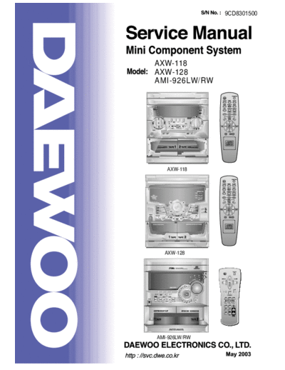
Image preview - the first page of the document

>> Download AXW-118 & 128 & AMI-926LW documenatation <<
Text preview - extract from the document
                        9CD8301500


AXW-118
AXW-128
A M I - 9 2 6 LW/ R W


    AXW-118


   AXW-128


AMI-926LW/RW
                                                        MINI COMPONENT SYSTEM
                                                                                      AXW-118
                                                                                      AXW-128
                                                                                      A M I - 9 2 6 LW/ R W


Table of Contents
SAFETY PRECAUTIONS.................................................................................2~3
ADJUSTMENTS................................................................................................4~5
EXPLODED VIEW AND PARTS LIST .................................................................6
        AXW-118.....................................................................................................................6~7
        AXW-128....................................................................................................................8~9
        AMI-926LW/RW.......................................................................................................10~11
WIRING DIAGRAM ........................................................................................... 12
BLOCK DIAGRAM .............................................................................................13
SCHEMATIC DIAGRAM ...............................................................................14~21
        MAIN.............................................................................................................................14
        TUNER .........................................................................................................................15
        TAPE.............................................................................................................................16
        CD ................................................................................................................................17
        FRONT(AXW-118/AXW-128)........................................................................................18
        FRONT(AMI-926LW/RW).............................................................................................19
        POWER........................................................................................................................20
PCB PATTERN LAYOUT .............................................................................21~26

ELECTRICAL PART LIST ............................................................................27~33


                                                                   1
Safety Precautions


                     2
Safety Precautions


                     3
Adjustments


              4
     Adjustments
       j
2. TAPE SECTION
                                                        Output Level
                                                        Measurement                                         Input Point
                                                           Point                                                                                Scope

                                                           R-CH                      47 kohm

                                                                                                                VTVM
                                             Input Level
                                             Measurement
                                             Point

                                                               L-CH                  47 kohm

Test Tape be used
                        Tape                                                            Contents                                                 Use
                      MTT-111N                                                           3 KHz                                          Tape Speed Adjustment
                      MTT-114N                                                           10 KHz                                        Head Azimuth Adjustment
                      MTT-5511                                                            Blank                                       Record Frequency Property
   HEAD ADJUSTMENT (AZIMUTH)
1. 10KHz test tape(example: MTT-114N) must be used for this adjustment.
2. Connect to VTVM or oscilloscope to the headphone jack or speaker terminal.
3. Press the play button.
4. Adjust the azimuth by using a screw driver to maintain the max. L&R output voltage.
5. Adjust tape A(1), tape B(2) respectively, Please secure the azimuth position by using locking paint.
   RECORDING BIAS OSCILLATOR FREQUENCY ADJUSTMENT
1. Connect the frequency counter to TP603, GND.
2. Press the REC button.
3. Adjust L603 to obtain 80 KHz
◦ Jabse Service Manual Search 2024 ◦ Jabse Pravopis ◦ onTap.bg ◦ Other service manual resources online : Fixya ◦ eServiceinfo