Service Manuals, User Guides, Schematic Diagrams or docs for : Daewoo TV cp093f
<< Back | HomeMost service manuals and schematics are PDF files, so You will need Adobre Acrobat Reader to view : Acrobat Download Some of the files are DjVu format. Readers and resources available here : DjVu Resources
For the compressed files, most common are zip and rar. Please, extract files with Your favorite compression software ( WinZip, WinRAR ... ) before viewing. If a document has multiple parts, You should download all, before extracting.
Good luck. Repair on Your own risk. Make sure You know what You are doing.
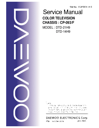
Image preview - the first page of the document

>> Download cp093f documenatation <<
Text preview - extract from the document
                                        SM No :TCP093FEF0

Service Manual
COLOR TELEVISION
CHASSIS : CP-093/F
MODEL : DTD-21H9
        DTD-14H9


  Caution
   : In this Manual, some parts can be changed for improving. their
     performance without notice in the parts list. So, if you need the
     latest parts information, please refer to PPL(Parts Price List)in
     Service Information Center(http://svc.dwe.co.kr)


  DAEWOO ELECTRONICS Corp.
  http : //svc.dwe.co.kr                             Jan. 2005
                                                    CP-093/F Service Manual

                                   CONTENTS
1. MAIN FEATURES                                                       2
 1.1 SPECIFICATIONS                                                    2
 1.1.1 GENERAL                                                         2
 1.1.2 EURO-SCART 1(21Pin)                                             3
 1.1.3 CHANNEL/FREQUENCY TABLE                                         4
2. SAFETY INSTRUCTION                                                  7
3. ALIGNMENT INSTRUCTIONS                                              8
 3.1 MICROCONTROLLER CONFIGURATION:SERVICE MODE                        8
 3.2 SERVICE MODE NADVIGATION                                          8
 3.3 MICROCONTROLLER CONFIGURATION:OPTION BITS                         8
 3.4 OPTION 1                                                          9
 3.5 OPTION 2                                                          9
 3.6 NVM default setting                                              10
4. TV SET ALIGNMENT                                                   12
 4.1 G2 ALIGNMENT                                                     12
 4.2 WHITE BALANCE                                                    12
 4.3 FOCUS                                                            12
 4.4 VERTICAL GEOMETRY                                                12
 4.5 HORIZONTAL PICTURE CENTRING                                      12
 4.6 EAST/WEST CORRECTION                                             12
 4.7 AGC                                                              13
5 IC DESCRIPTION                                                      14
          ///
 5.1 UOC Series                                                       14
 5.1.1 IC MARKING AND VERSION                                         14
 5.1.2 BLOCK DIAGRAM                                                  15
 5.1.3 PINNING                                                        16
 5.1.4 FEATURES                                                       17
 5.2 TDA8944J STEREO AUDIO AMPLIFIER                                  22
 5.2.1 FEATURES                                                       23
 5.3 TDA8357J VERTICAL AMPLIFIER                                      25
 5.3.1 TDA8357J                                                       25
 5.4 TDA6107AJE                                                       28
 5.4.1 Features                                                       28
 5.4.2 Pin description                                                28
 5.5 24WC16-16KB EEPROM                                               29
 5.6 STR-F6756/4                                                      30
 5..6.1 Functions of Each Terminal                                    30
 5..6.2 Block Diagram(Connection diagram)                             30
 5..6.3 CONTROL PART - ELECTRICAL CHARACTERISTICS                     33
6. SPECIFICATIONS                                                     34
7. SERVICE PARTS LIST                                                 37
8. EXPLODED VIEW                                                      51
9. PRINTED CIRCUIT BOARD                                              53
10. SCHEMATIC DIAGRAM                                                 55
                                                                    CP-093/F Service Manual

1. MAIN FEATURES

1.1   SPECIFICATIONS

1.1.1 GENERAL

        TV standard                PAL - SECAM B/G D/K, PAL I/I, SECAM L/L'
        Colour system        Tuner PAL, SECAM
                             AV    PAL, SECAM, PAL 60, NTSC M, NTSC 4.43
        Sound system               NICAM B/G, I, D/K, L,
                                   FM 2Carrier B/G, D/K
        Power                      14" : 66W
        consumption                21" : 74W
        Sound Output               14" : 1.5W x 2 (at 60% mod, 10% THD)
        Power                      20" : 3W x 2 (at 60% mod, 10%THD)
        Speaker                    14" : 3W 8 ohm x 2 (No sound when AV2 PCB
                                   21" : 5W 8 ohm x2 is not connected)
        Teletext system            10 pages memory FASTEXT (FLOF or TOP)
        Aerial input               75 ohm unbalanced
        Channel coverage           Off-air channels, S-cable channels and hyperband
        Tuning system              frequency synthesiser tuning system
        Visual screen size         14" : 33cm
                                   21" : 51cm
        Channel indication         On Screen Display
        Program Selection          100 programmes
        Aux. terminal              - EURO-SCART : Audio / Video In and Out, R/G/B
                                   In, Slow and Fast switching.
                                   -SPDIF and Audio L/R out at back of cabinet.
                                   (14")
                                   - Headphone jack on front of cabinet
                                   (21")
                                   - AV2 : Video and Audio L/R out, Headphone jack
                                   at side of cabinet.
        Remote Control             R-52C03
        Unit


                                             2
                                                                    CP-093/F Service Manual

1.1.2 EURO-SCART 1 (21 Pin)
 Pin   Signal Description   Matching value
1      Audio Output Right   0.5 Vrms, Impedance < 1 k, ( RF 54% Mod )
2      Audio Input Right    0.5 Vrms, Impedance > 10 k
3      Audio Output Left    0.5 Vrms, Impedance < 1 k, ( RF 54% Mod )
4      Audio Earth
5      Blue Earth
6      Audio Input Left     0.5 Vrms, Impedance > 10 k
7      Blue Input           0.7 Vpp
◦ Jabse Service Manual Search 2024 ◦ Jabse Pravopis ◦ onTap.bg ◦ Other service manual resources online : Fixya ◦ eServiceinfo