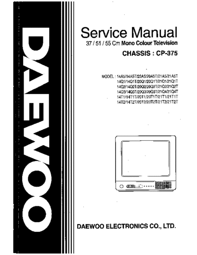
Service Manuals, User Guides, Schematic Diagrams or docs for : Daewoo TV daewoo-cp-375
<< Back | HomeMost service manuals and schematics are PDF files, so You will need Adobre Acrobat Reader to view : Acrobat Download Some of the files are DjVu format. Readers and resources available here : DjVu Resources
For the compressed files, most common are zip and rar. Please, extract files with Your favorite compression software ( WinZip, WinRAR ... ) before viewing. If a document has multiple parts, You should download all, before extracting.
Good luck. Repair on Your own risk. Make sure You know what You are doing.
Image preview - the first page of the document

>> Download daewoo-cp-375 documenatation <<
Text preview - extract from the document
   Specifications

CRT                 A34JLL90X01,A34EAC01X06,A34EFU13X01
                       (OEC)       (PHILIPS)   (POLKOLOR)
System              C14M7E : PAL-B/G for West Europe (Non-TXT)
                    C14M7F : PAL-B/G, SECAM-L for France (Non-TXT)
                    C14T7B : PAL- I for U.K (TXT)
                    C14M7B : PAL- I for U.K (Non-TXT)
                    C14T7L : PAL - I/I for Ireland (TXT)
                    C14M7L : PAL - I/I for Ireland (Non-TXT)
Main Voltage        230V AC, 50Hz
Power Consumption   Stand-by mode : 8 Watts
                    Normal operating mode : 39Watts
Sound output        1.5 Watts, 10 % THD at RF 60 % mod.
Speaker             3W 16 ohm x 1 EA
Antenna             75 ohm unbalanced input
Impedance
Tuning system       VS( voltage synthesis ) tuning
Tuner               3303KHC (C14M7E, C14M7F, C14T7L, C14M7L)
                               BAND I    : CH2 - CH4
                               BAND III : CH5 - CH12
                               CABLE BAND : S1' - S3' , S1 - S20
                               HYPER BAND : S21 - S41
                               BAND IV, V : CH21 - CH69
                    DT2-IV17D (C14T7B, C14M7B )
                               BAND IV, V : CH21 - CH69
Number of           70 programs
program
Aux. Terminal       21 pin EURO-SCART jack
                    ( AV input, TV output, RGB input, S-VHS input )
                    RCA type AV input jack
                    Headphone jack (3.5 mm )
Remote controller   RM-01A01 with 2 "AA" type batteries
Teletext            8 pages memory TOP & FLOF
(option)                 : English, German/Dutch/Flemish, French, Italian,
                           Spanish/Portuguese, Swedish/Finnish/Danish, Czech/Slovak
OSD language        -TXT Model : English,French,German,Italian,Spanish
                    -Non-TXT Model : English,French,German,Italian,Spanish, Russian


                                                     1
    Safety Instruction

WARNING: Only competent service personnel may carry out work involving the testing or repair of
this equipment.


  X-RAY RADIATION PRECAUTION
1. Excessive high voltage can produce potentially           2. The only source of X-RAY Radiation in this TV
   hazardous X-RAY RADIATION.To avoid such                     receiver is the picture tube.For continued X-RAY
   hazards, the high voltage must not exceed the               RADIATION protection,the replacement tube
   specified limit. The nominal value of the high              must be exactly the same type tube as specified
   voltage of this receiver is 22-23   at max beam             in the parts list.
   current. The high voltage must not, under any
   circumstances, exceed 27.5 .
   Each time a receiver requires servicing, the high
   voltage should be checked. It is important to use
   an accurate and reliable high voltage meter.


  SAFETY PRECAUTION
1. Potentials of high voltage are present when this         2. If any Fuse in this TV receiver is blown, replace it
   receiver is operating. Operation of the receiver            with the FUSE specified in the Replacement
   outside the cabinet or with the back board                  Parts List.
   removed involves a shock hazard from the                 3. When replacing a high wattage resistor(oxide
   receiver.                                                   metal film resistor)in circuit board, keep the
  1) Servicing should not be attempted by anyone               resistor 10mm away from circuit board.
     who is not thoroughly familiar with the                4. Keep wires away from high voltage or high
     precautions necessary when working on high-               temperature components.
     voltage equipment.                                     5. This receiver must operate under AC230 volts,
  2) Discharge the high potential of the picture tube          50Hz. NEVER connect to DC supply or any other
     before handling the tube. The picture tube is             power or frequency.
     highly evacuated and if broken, glass
     fragments will be violently expelled.


  PRODUCT SAFETY NOTICE
Many electrical and mechanical parts in this have           identified by designated symbol on the parts list.
special safety-related characteristics. These               Before replacing any of these components, read the
characteristics are often passed unnoticed by a             parts list in this manual carefully. The use of
visual inspection and the X-RAY RADIATION                   substitute replacement parts which do not have the
protection afforded by them cannot necessarily be           same safety characteristics as specified in the parts
obtained by using replacement components rated              list may create X-RAY Radiation.
for higher voltage,wattage,etc. Replacement parts
which have these special safety characteristics are
identified in this manual and its supplements,
electrical components having such features are


                                                        3
Circuit block Diagram


                        4
     Alignment Instructions

    Remark: A service remocon(R-30SVC) is needed to align the set.
1. AFT

1.1 Standard B/G,D/K,I and L
 1) Set a Signal Generator with
    - RF FREQUENCY = 38.9 MHz,
    - RF OUTPUT LEVEL = 80
◦ Jabse Service Manual Search 2024 ◦ Jabse Pravopis ◦ onTap.bg ◦ Other service manual resources online : Fixya ◦ eServiceinfo