Service Manuals, User Guides, Schematic Diagrams or docs for : Daewoo TV dty-28a8_28a6_28a7_esm
<< Back | HomeMost service manuals and schematics are PDF files, so You will need Adobre Acrobat Reader to view : Acrobat Download Some of the files are DjVu format. Readers and resources available here : DjVu Resources
For the compressed files, most common are zip and rar. Please, extract files with Your favorite compression software ( WinZip, WinRAR ... ) before viewing. If a document has multiple parts, You should download all, before extracting.
Good luck. Repair on Your own risk. Make sure You know what You are doing.
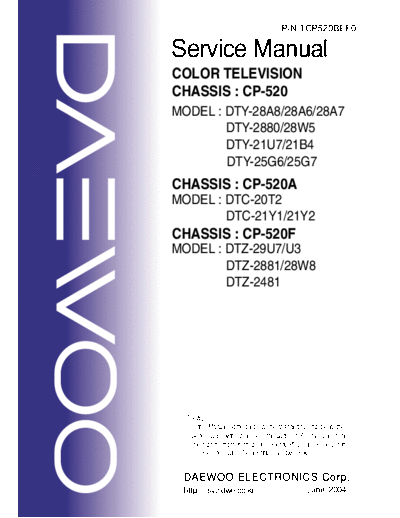
Image preview - the first page of the document

>> Download dty-28a8_28a6_28a7_esm documenatation <<
Text preview - extract from the document
                                         P/N:TCP520BEF0

Service Manual
COLOR TELEVISION
CHASSIS : CP-520
MODEL : DTY-28A8/28A6/28A7
        DTY-2880/28W5
        DTY-21U7/21B4
        DTY-25G6/25G7
CHASSIS : CP-520A
MODEL : DTC-20T2
        DTC-21Y1/21Y2
CHASSIS : CP-520F
MODEL : DTZ-29U7/U3
        DTZ-2881/28W8
        DTZ-2481


  Caution
  : In this Manual, some parts can be changed for improving. their
    performance without notice in the parts list. So, if you need the
    latest parts information, please refer to PPL(Parts Price List)in
    Service Information Center(http://svc.dwe.co.kr)


 DAEWOO ELECTRONICS Corp.
 http : //svc.dwe.co.kr                             June. 2004
                                                                                              CP-520/520A/520F Service Manual

                                                             CONTENTS

DOCUMENT HISTORY................................................................................................................. 3
1     MAIN FEATURES.................................................................................................................. 4
    1.1 SPECIFICATIONS.......................................................................................................... 4
      1.1.1 GENERAL................................................................................................................ 4
      1.1.2 EURO-SCART 1 (21 Pin)......................................................................................... 4
      1.1.3 EURO-SCART 2 (21 Pin)......................................................................................... 5
    1.2 CHANNEL/FREQUENCY TABLE .................................................................................. 6
2     SAFETY INSTRUCTION ....................................................................................................... 9
3     ALIGNMENT INSTRUCTIONS ............................................................................................ 10
    3.1 MICROCONTROLLER CONFIGURATION : SERVICE MODE ................................... 10
    3.2 SERVICE MODE NAVIGATION ................................................................................... 10
    3.3 MICROCONTROLLER CONFIGURATION : OPTION BITS........................................ 10
    3.4 OPTION 1 ..................................................................................................................... 11
    3.5 OPTION 2 ..................................................................................................................... 11
    3.6 NVM DEFAULT SETTING............................................................................................ 12
    3.7 TV SET ALIGNMENT ................................................................................................... 14
      3.7.1 G2 ALIGNMENT .................................................................................................... 14
      3.7.2 WHITE BALANCE ................................................................................................. 14
      3.7.3 FOCUS .................................................................................................................. 14
      3.7.4 VERTICAL GEOMETRY........................................................................................ 14
      3.7.5 HORIZONTAL PICTURE CENTRING ................................................................... 14
      3.7.6 EAST / WEST CORRECTION ............................................................................... 14
      3.7.7 AGC ....................................................................................................................... 15
4     IC DESCRIPTION ................................................................................................................ 16
    4.1 UOC III SERIES ............................................................................................................. 16
       4.1.1 IC MARKING AND VERSION................................................................................ 16
    4.2 TDA8946J STEREO AUDIO AMPLIFIER .................................................................... 24
       4.2.1 FEATURES............................................................................................................ 25
    4.3 TDA8358J VERTICAL AMPLIFIER ............................................................................. 27
       4.3.1 TDA8358J.............................................................................................................. 27
    4.4 TDA6107AJF................................................................................................................ 29
       4.4.1 Features................................................................................................................. 29
       4.4.2 Pin description ....................................................................................................... 29
    4.5 24WC16 - 16 KB EEPROM .......................................................................................... 30
    4.6 STR - F6653 ................................................................................................................. 31
       4.6.1 GENERAL DESCRIPTION .................................................................................... 31
       4.6.2 FEATURES............................................................................................................ 31
       4.6.3 BLOCK DIAGRAM................................................................................................. 31
       4.6.4 PIN DESCRIPTION ............................................................................................... 32
       4.6.5 CONTROL PART - ELECTRICAL CHARACTERISTICS....................................... 32
       4.6.6 MOSFET ELECTRICAL CHARACTERISTICS ...................................................... 33
5     CIRCUIT DESCRIPTION ..................................................................................................... 34
    5.1 BLOCK DIAGRAM ....................................................................................................... 34
    5.2 FUNCTIONAL DESCRIPTION OF VIDEO PROCESSOR ........................................... 35
      5.2.1 Vision IF amplifier .................................................................................................. 35
      5.2.2 QSS sound circuit .................................................................................................. 35
      5.2.3 FM demodulator..................................................................................................... 35
      5.2.4 Audio input selector and volume contro ................................................................. 36
DTV R&D Europe                                                                                                                     1
                                                                                               CP-520/520A/520F Service Manual

        5.2.4.1 STEREO AND AV STEREO VERSIONS ........................................................... 36
        5.2.4.2 MONO VERSIONS ............................................................................................ 36
      5.2.5 CVBS and Y/C input signal selection..................................................................... 36
        5.2.5.1 ALL VERSIONS ................................................................................................. 36
      5.2.6 Synchronisation circuit ........................................................................................... 37
      5.2.7 Horizontal and vertical drive................................................................................... 38
      5.2.8 Chroma, luminance and feature processing .......................................................... 38
      5.2.9 Colour decoder ...................................................................................................... 39
      5.2.10 RGB output circuit.................................................................................................. 40
      5.2.11 I2C-BUS USER INTERFACE DESCRIPTION ....................................................... 42
    5.3 GENERAL DESCRIPTION OF THE TV SOUND OF SOUND PROCESSOR.............. 42
      5.3.1 Supported standards ............................................................................................. 43
    5.4 FUNCTIONAL DESCRIPTION SOUND PROCESSOR ............................................... 44
      5.4.1 The UOC III TV Sound Concept ............................................................................ 44
      5.4.2 Functional Overview Of the digital controller sound part........................................ 45
      5.4.3 Demodulator and decoder ..................................................................................... 46
6     SERVICE PARTS LIST ....................................................................................................... 49
    6.1 DTY-28A8FZF-S........................................................................................................... 49
    6.2 DTC-20T2FZS-S........................................................................................................... 54
    6.3 DTC-21Y1FZF-S........................................................................................................... 59
    6.4 DTZ-29U7FZS-S........................................................................................................... 64
7     EXPLODED VIEW ............................................................................................................... 69
    7.1 DTY-28A8 ..................................................................................................................... 69
    7.2 DTY-2880 ..................................................................................................................... 70
    7.3 DTY-21U7..................................................................................................................... 71
    7.4 DTC-20T2..................................................................................................................... 72
    7.5 DTC-21Y1..................................................................................................................... 73
    7.6 DTZ-29U7 ..................................................................................................................... 74
    7.7 DTZ-2881...................................................................................................................... 75
    7.8 DTZ-2481...................................................................................................................... 76
8     PRINTED CIRCUIT BOARD................................................................................................ 77
    8.1 4859809693(CP-520) ................................................................................................... 77
    8.2 4859809893(CP-520A)................................................................................................. 78
    8.3 4859809993(CP-520F) ................................................................................................. 79
9     SCHEMATIC DIAGRAM...................................................................................................... 80
    9.1 CP-520.......................................................................................................................... 80
    9.2 CP-520A ....................................................................................................................... 81
    9.3 CP-520F ....................................................................................................................... 82


DTV R&D Europe                                                                                                                      2
                                                      CP-520/520A/520F Service Manual

DOCUMENT HISTORY


VERSION  DATE                                 COMMENTS
 V1.00  12/05/04 Creation of document (Author JS KIM) for project CP520 50Hz TV.


DTV R&D Europe                                                                     3
                                                           CP-520/520A/520F Service Manual

1     MAIN FEATURES

1.1    SPECIFICATIONS

1.1.1 GENERAL

         TV standard                PAL - SECAM B/G D/K, PAL I/I, SECAM L/L'
         Colour system        Tuner PAL, SECAM
                              AV    PAL, SECAM, PAL 60, NTSC M, NTSC 4.43
         Sound system               NICAM B/G, I, D/K, L,
                                    FM 2Carrier B/G, D/K
         Power                      20",21" : 49W
         consumption                21" (4:3) Flat : 59W
                                    28" (4:3) : 69W
                                    28"(16:9) : 69W
         Sound Output               20" ~ 24" : 4.5W x 2 (at 60% mod, 10% THD)
         Power                      25" ~ 29" : 7W x 2 (at 60% mod, 10%THD)
         Speaker                    20" ~ 24" : 7.5W 8 ohm x 2
                                    25" ~ 29" : 12W 8 ohm x2
         Teletext system            10 pages memory FASTEXT (FLOF or TOP)
         Aerial input               75 ohm unbalanced
         Channel coverage           Off-air channels, S-cable channels and hyperband
         Tuning system              frequency synthesiser tuning system
         Visual screen size         20" : 48cm
                                    21" : 51cm
                                    28" : 66cm
         Channel indication         On Screen Display
         Program Selection          100 programmes
         Aux. terminal              EURO-SCART 1 : Audio / Video In and Out, R/G/B
                                    In, Slow and Fast switching.
                                    EURO-SCART 2 : Audio / Video In and Out, SVHS
                                    In.
                                    AV3 : Audio-Video Jack on front of cabinet.
                                    Headphone jack (3.5 mm) on front of cabinet
                                    SVHS3 (option) : Jack on front of cabinet
◦ Jabse Service Manual Search 2024 ◦ Jabse Pravopis ◦ onTap.bg ◦ Other service manual resources online : Fixya ◦ eServiceinfo