Service Manuals, User Guides, Schematic Diagrams or docs for : Daewoo Video-DVD DAEWOO_DV-K34-54-84NY_K24-44-74-82-87_K26-46-27-47N_K79-84N_K26-46N_K59N_K76-77N_K-86N_DV-K81N_VCR
<< Back | HomeMost service manuals and schematics are PDF files, so You will need Adobre Acrobat Reader to view : Acrobat Download Some of the files are DjVu format. Readers and resources available here : DjVu Resources
For the compressed files, most common are zip and rar. Please, extract files with Your favorite compression software ( WinZip, WinRAR ... ) before viewing. If a document has multiple parts, You should download all, before extracting.
Good luck. Repair on Your own risk. Make sure You know what You are doing.
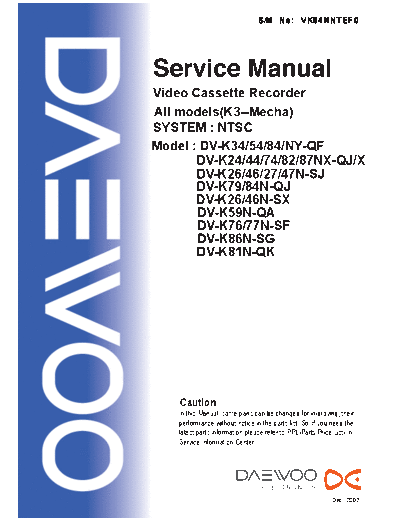
Image preview - the first page of the document

>> Download DAEWOO_DV-K34-54-84NY_K24-44-74-82-87_K26-46-27-47N_K79-84N_K26-46N_K59N_K76-77N_K-86N_DV-K81N_VCR documenatation <<
Text preview - extract from the document
                                  S/M No: VK84NNT EF 0


Video Cassette Recorder
All models(K3--Mecha)
SYSTEM : NTSC
Model : DV-K34/54/84/NY-QF
       DV-K24/44/74/82/87NX-QJ/X
       DV-K26/46/27/47N-SJ
       DV-K79/84N-QJ
       DV-K26/46N-SX
       DV-K59N-QA
       DV-K76/77N-SF
       DV-K86N-SG
       DV-K81N-QK


    Caution
   : In this Manual, some parts can be changed for improving, their
     performance without notice in the parts list. So, if you need the
     latest parts information,please refer to PPL(Parts Price List) in
     Service Information Center.


                                                             Dec . 2002
TABLE OF CONTENTS
SPECIFICATION .......................................................................................................... 2
GENERAL ADJUSTMENTS ............................................................................................. 3
TROUBLESHOOTING GUIDES ....................................................................................... 4
 POWER CIRCUIT ................................................................................................................................4
 SERVO / SYSCON / LOGIC CIRCUIT ....................................................................................................5
 VIDEO CIRCUIT .................................................................................................................................12
 AUDIO CIRCUIT (Hi-Fi MODEL) ..........................................................................................................16
 AUDIO CIRCUIT (2 / 4 HEAD MODEL) .................................................................................................21
 EXTENDED DATA SERVICE CIRCUIT .....................................................................................................24

WAVEFORMS ............................................................................................................. 25
CIRCUIT DIAGRAM ...................................................................................................... 29
 INTERCONNECT WIRING DIAGRAM ....................................................................................................              29
 POWER SUPPLY SCHEMATIC DIAGRAM ...............................................................................................                30
 SYSCON CIRCUIT DIAGRAM ...............................................................................................................        31
 VIDEO/AUDIO SCHEMATIC DIAGRAM (2/4 HEAD) ................................................................................                     32
 VIDEO/AUDIO SCHEMATIC DIAGRAM (Hi-Fi) ........................................................................................                33
 PIF SCHEMATIC DIAGRAM (2/4 HEAD) ................................................................................................             34
 HI-FI SCHEMATIC DIAGRAM..............................................................................................................         35
 PIF&MPX SCHEMATIC DIAGRAM (Hi-Fi) .............................................................................................               36

INSTRUMENT DISASSEMBLY .......................................................................................... 37
ELECTRICAL PARTS LIST ............................................................................................... 43


                                                                               1
 SPECIFICATION

                                                   120 Volts AC 60Hz

                                                     DV-K34NY-QF        K54NY-QF     K84NY-QF     K24NX-QJ/X
                                                        K44NX-QJ/X      K74NX-QJ/X   K82NX-QJ/X   K87NX-QJ/X
                                                        K26N-SJ         K46N-SJ      K27N-SJ      K47N-SJ
                                                        K79N-QJ        K84N-QJ K26N-SX      K46N-SX
 Power Input
                                                       K59N-QA        K76N-SF K77N-SF      K86N-SG K81N-QK
                                                         DV-K* : INITIAL NUMBER IDENTIFICATION

                                                                   POWER INPUT       2HD   4HD    Hi-Fi
                                                                                     2.3    4.5    7.8

                                                   17 Watts (4-head Hi-Fi)
 Power Consumption
                                                   17 Watts (4-head, 2-head)
 Operating Temperature                             5 degree C to 40 degree C (41 degree F to 104 degree F)
 Storage Temperature                               -30 degree C to 65 degree C (-22 degree F to 149 degree F)
 Weight                                            7.8 Ibs : Net (9.5 Ibs : Gross)
 Dimensions                                        14.2 X 3.6 X11.0 Inches
                                                   4-head Hi Fi: Four video record/playback heads Rotary helical scan
                                                                    Luma: FM recording
                                                                    Chroma: converted subcarrier phase shifted recording
                                                                  Two audio record/playback heads
                                                                    Rotary helical scan, 2 channels FM recording
 Recording System                                  4-head:       Four video record/playback heads Rotary helical scan
                                                                    Luma: FM recording
                                                                    Chroma: converted subcarrier phase shifted recording
                                                   2-head:      Two video record/playback heads Rotary helical scan
                                                                    Luma: FM recording
                                                                    Chroma: converted subcarrier phase shifted recording
 Video Signal                                      EIA standard; NTSC color
 Antenna                                           75 ohm input impedance
 Video Signal Level                                1Vp-p (140 IRE standard)
 Audio Input Impedance                             More than 47K ohm
 Audio Output Impedance                            Less than 1.5K ohm
                                                   SP: 33.35mm/sec.
 Tape Speed
                                                   SLP: 11.13mm/sec
                                                   T-60: 3 hours/ EP (SLP) mode
 Maximum Recording Time
                                                   T120: 6 hours/ EP (SLP) mode
 Fast Forward/Rewind Time                          3 minutes (T-120 tape)
 Tuning System                                     Auto Program/Cable Compatible/Frequency Synthesis (FS)

Note: Specifications are subject to change without notice.


                                                             2
 GENERAL ADJUSTMENTS
PG (Pulse Generator) Shifter Adjustment (Fig. 7)

   Test Points:    PT01 PIN 3             Main
                   Video Out Jack         Rear Panel
   Adjust:         R595 (PG Shifter)      Main


The Pulse Generator (PG) Shifter determines the video head switching point during playback.
Misadjustment of the PG Shifter may cause head switching noise in the picture and/or vertical jitter.

1. Load the instrument with an alignment tape and play back the color bar signal or monoscope signal.
2. Connect channel-1 scope probe (1V/div.: 50
◦ Jabse Service Manual Search 2024 ◦ Jabse Pravopis ◦ onTap.bg ◦ Other service manual resources online : Fixya ◦ eServiceinfo