Service Manuals, User Guides, Schematic Diagrams or docs for : Daewoo Сhassis CN CN-220B & C CN-220B & C
<< Back | HomeMost service manuals and schematics are PDF files, so You will need Adobre Acrobat Reader to view : Acrobat Download Some of the files are DjVu format. Readers and resources available here : DjVu Resources
For the compressed files, most common are zip and rar. Please, extract files with Your favorite compression software ( WinZip, WinRAR ... ) before viewing. If a document has multiple parts, You should download all, before extracting.
Good luck. Repair on Your own risk. Make sure You know what You are doing.
Image preview - the first page of the document
>> Download CN-220B & C documenatation <<
Text preview - extract from the document
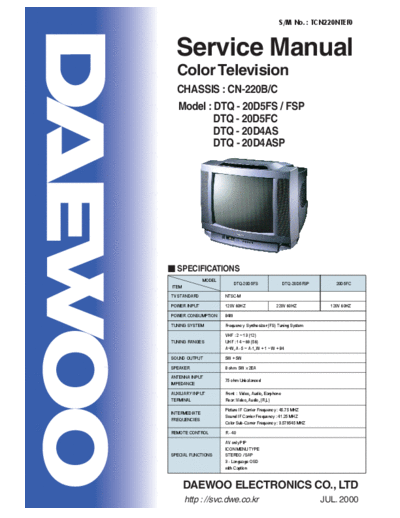
S/M No. : TCN220NTEF0
Service Manual
Color Television
CHASSIS : CN-220B/C
Model : DTQ - 20D5FS / FSP
DTQ - 20D5FC
DTQ - 20D4AS
DTQ - 20D4ASP
SPECIFICATIONS
MODEL
DTQ-20D5FS DTQ-20D5FSP 20D5FC
ITEM
TV STANDARD NTSC-M
POWER INPUT 120V 60HZ 220V 60HZ 120V 60HZ
POWER CONSUMPTION 84W
TUNING SYSTEM Frequency Synthesizer (FS) Tuning System
VHF : 2 ~ 13 (12)
TUNING RANGES UHF : 14 ~ 69 (56)
A~W, A- 5 ~ A-1, W + 1 ~ W + 84
SOUND OUTPUT 5W + 5W
SPEAKER 8 ohm 5W x 2EA
ANTENNA INPUT
75 ohm Unbalanced
IMPEDANCE
AUXILIARY INPUT Front : Video, Audio, Earphone
TERMINAL Rear: Video, Audio, (R,L)
Picture IF Carrier Frequency : 45.75 MHZ
INTERMEDIATE
Sound IF Carrier Frequency : 41.25 MHZ
FREQUENCIES
Color Sub-Carrer Frequency : 3.579545 MHZ
REMOTE CONTROL R - 40
AV only PIP
ICON MENU TYPE
SPECIAL FUNCTIONS STEREO / SAP
3 - Language OSD
with Caption
DAEWOO ELECTRONICS CO., LTD
http : //svc.dwe.co.kr JUL. 2000
TABLE OF CONTENTS
SAFETY INSTRUCTION .................................................................................................................. 2
SPECIFICATIONS ............................................................................................................................ 3
CIRCUIT BLOCK DIAGRAM ........................................................................................................... 5
ALIGNMENT INSTRUCTION ........................................................................................................... 6
Your Remote Control ........................................................................................................................ 6
Service Mode Adjustment ................................................................................................................. 7
Assembly Adjustment ....................................................................................................................... 8
SCHEMATIC DIAGRAM .................................................................................................................. 12
EXPLODED VIEW ............................................................................................................................ 12
PRINTED CIRCUIT BOARD ............................................................................................................ 13
SERVICE PARTS LIST .................................................................................................................... 14
The Different Parts List ..................................................................................................................... 21
APPENDIX (" Appendix is provided only by internet [http://svc.dwe.co.kr] ")
IC DESCRIPTION ........................................................................................................................... 1
Trouble Shooting Guide ............................................................................................................... 11
1. No Power .................................................................................................................................... 11
2. No Picture ................................................................................................................................... 12
3. No Sound .................................................................................................................................... 13
4. CH Don' Stop .............................................................................................................................
t 14
5. No Color ..................................................................................................................................... 15
6. No Vertical Deflection ................................................................................................................. 15
7. No On-Screen Display ................................................................................................................ 16
8. Remote Control Does not Operate ............................................................................................. 16
1
SAFETY INSTRUCTION
WARNING : Only competent service personnel may carry out work involving the testing or repair of this equipment
X-RAY RADIATION PRECAUTION
1. Excessive high voltage can produce potentially hazardous X-RAY RADIATION. To avoid such hazards, the high
voltage must not exceed the specified limit. The nominal value of the high voltage of this receiver is 22-23 kV (14" or
)
24-26 kV (20"- 21" at max beam current. The high voltage must not, under any circumstances, exceed 27.5 kV (14"
) ,
20" 29KV (21" Each time a receiver requires servicing, the high voltage should be checked. It is important to use an
), ).
accurate and reliable high voltage meter.
2. The only source of X-RAY Radiation in this TV receiver is the picture tube. For continued X-RAY RADIATION
protection, the replacement tube must be exactly the same type tube as specified in the parts list.
SAFETY PRECAUTION
1. Potentials of high voltage are present when this receiver is operating. Operation of the receiver outside the cabinet or
with the back cover removed involves a shock hazard from the receiver.
1)Servicing should not be attempted by anyone who is not thoroughly familiar with the precautions necessary when
working on high voltage equipment.
2)Discharge the high potential of the picture tube before handling the tube. The picture tube is highly evacuated and if
broken, glass fragments will be violently expelled.
2. If any Fuse in this TV receiver is blown, replace it with the FUSE specified in the Replacement Parts List.
3. When replacing a high wattage resistor (oxide metal film resistor) in circuit board, keep the resistor body 10 mm away
from the circuit board.
4. Keep wires away from high voltage or high temperature components.
5. This receiver must operate under AC 230 volts, 5O Hz. NEVER connect to a DC supply of any other voltage or
frequency.
PRODUCT SAFETY NOTICE
Many electrical and mechanical parts in this equipment have special safety-related characteristics. These characteristics are
often passed unnoticed by a visual inspection and the X-RAY RADIATION protection afforded by them cannot necessarily be
obtained by using replacement components rated for higher voltage, wattage, etc. Replacement parts which have these spe-
cial safety characteristics are identified in this manual and its supplements, electrical components having such features are
identified by designated symbol on the parts list. Before replacing any of these components, read the parts list in this manual
carefully. The use of substitutes replacement parts which do not have the same safety characteristics as specified in the parts
list may create X-RAY Radiation.
2
SPECIFICATIONS
CN-220B Chassis
MODEL
DTQ-20D5FS DTQ-20D5FSP DTQ-20D5FC
ITEM
TV STANDARD NTSC-M
POWER INPUT 120V 60HZ 220V 60HZ 120V 60HZ
POWER CONSUMPTION 84W
TUNING SYSTEM Frequency Synthesizer (FS) Tuning System
VHF : 2 ~ 13 (12)
TUNING RANGES UHF : 14 ~ 69 (56)
A~W, A- 5 ~ A-1, W + 1 ~ W + 84
SOUND OUTPUT 5W + 5W
SPEAKER 8 ohm 5W x 2EA
ANTENNA INPUT IMPED-
75 ohm Unbalanced
ANCE
AUXILIARY INPUT TERMI- Front : Video, Audio, Earphone
NAL Rear: Video, Audio, (R,L)
Picture IF Carrier Frequency : 45.75 MHZ
INTERMEDIATE FREQUEN-
Sound IF Carrier Frequency : 41.25 MHZ
CIES
Color Sub-Carrer Frequency : 3.579545 MHZ
REMOTE CONTROL R - 40
AV only PIP
ICON MENU TYPE
SPECIAL FUNCTIONS STEREO / SAP
3 -Language OSD
with Caption
3
SPECIFICATIONS
CN-220C Chassis
MODEL
DTQ-20D4AS DTQ-20D4ASP
ITEM
TV STANDARD NTST-M
POWER INPUT 120V 60HZ 220V 60HZ
POWER CONSUMPTION 84W
TUNING SYSTEM Frequency Synthesizer (FS) Tuning System
TV VHF(L) : CH 2 ~ CH 6
UHF(H) : CH 7 ~ CH 13
UHF : CH 14 ~ CH 69
CATV VHF(L) : 5A, A, B, A-5 - A-1
TUNING RANGES
CH 2 - CH 6
VHF(H) : C - W + 11
CH 7 - CH 13
UHF : W + 12 - W + 84
SOUND OUTPUT 5W + 5W
SPEAKER 8 ohm 5W x 2EA
ANTENNA INPUT IMPEDANCE 75 ohm Unbalanced
Front : Video, Audio, Earphone
AUXILIARY INPUT TERMINAL
Rear: Video, Audio, (R,L)
Picture IF Carrier Frequency : 45.75 MHZ
INTERMEDIATE FREQUEN-
Sound IF Carrier Frequency : 41.25 MHZ
CIES
Color Sub-Carrer Frequency : 3.579545 MHZ
REMOTE CONTROL R - 40
1) ICON MENU TYPE
2) 3-Language OSD
SPECIAL FUNCTIONS
3) WITH CAPTION
4) CH LABEL
4
A/V IN 1 A/V IN 2
V A H V L R 9V 5V
RF EARPHONE
5V 33V
SOUND IC
SOUND
TUNER MAIN IC MSP3430G
AMP
DT5 -NF20F DCT814B
TDA7266
SCL SDA
TRAP
SCL SDA
SAW BPF
(1) (2) 14V
IR FI LTER IF DET.
OUT
PIP IC
SW1 ~ SCL SDA9388
SW5 SDA RGB CVS SCL
u -COM IC
RGB SDA VIDEO
LC8632 40 OSD RGB
AMP
SCL
EEPROM 5V TDA 6103Q
5
SDA
X-RAY
9V
CIRCUIT BLOCK DIAGRAM
SOUND SCL (1)
5V (2)
SOUND SDA
220V
OCP VERTICAL HOR. OUTPUT 10V Screen Fouse H. V.
LA7841 2SD2499
26V 14V
28V FBT
POWER IC
2SK2564
DEFLECTION YOKE HEATER
SMPS TRANS
TSM-3541A5
DPM001T1(110V), DP001T1A(220V)
ALIGNMENT INSTRUCTIONS
Your Remote Control
1. POWER
Use this button to turn your TV on or off.
2. 0 - 9
Use these buttons to change channels.
3. MUTE
POWER
Use to turn the TV's sound on and off.
1 4. DISPLAY
Use this buttons to display the channel
1 2 3
number and status.
4 5 6 5. CH
2 Use these buttons to change channels on your
7 8 9 TV, or select items in the menu system.
6. VOL
DISPLAY 0 MUTE
Use these buttons to change your TV's volume,
4 3 to activate selections in the menu system, or to
change audio and video settings.
CH
7. TV/VIDEO
MENU 5
7 Use this button to select main picture source.
VOL VOL 8. MTS
6 6 Use this button to select one mode of Mono,
Stereo or SAP.
9. PREVIOUS
5 Use this button to return previous channel you were
CH
8 watching.
TV/VIDEO MTS PREVIOUS
7 11 10. PIP
PIP STILL SWAP
Use this button to turn PIP on/off.
10 12 11. STILL
SCREEN POSITION INPUT Use this button to still PIP source.
11 12. SWAP
14 15 Use this button to exchange PIP source and main
source.
13
13. SCREEN
Use this button to change the size of the picture
(from normal 4:3 to WIDE, ZOOM, and the original
4:3 in turn).
14. POSITION
Use this button to change position of pip on your TV.
15. INPUT
Use this button to select PIP source (TV/VIDEO).
6
ALIGNMENT INSTRUCTIONS
SERVICE MODE ADJUSTMENTS
Follow the steps below whenever service adjustment is required. See Table- A and Table- B to determine if
service adjustments are required.
1) How to enter the service mode using the user remote control.
◦ Jabse Service Manual Search 2026 ◦ Jabse Pravopis ◦ onTap.bg ◦ Other service manual resources online : Fixya ◦ eServiceinfo