Service Manuals, User Guides, Schematic Diagrams or docs for : Daewoo Сhassis CP CP-371 CP-371

<< Back | Home

Most service manuals and schematics are PDF files, so You will need Adobre Acrobat Reader to view : Acrobat Download Some of the files are DjVu format. Readers and resources available here : DjVu Resources
For the compressed files, most common are zip and rar. Please, extract files with Your favorite compression software ( WinZip, WinRAR ... ) before viewing. If a document has multiple parts, You should download all, before extracting.
Good luck. Repair on Your own risk. Make sure You know what You are doing.


Image preview - the first page of the document
CP-371


>> Download CP-371 documenatation <<

Text preview - extract from the document
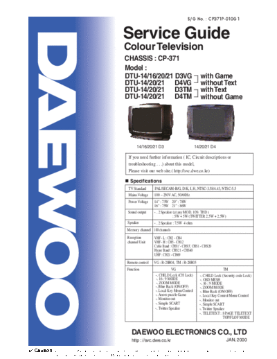
                                                                                                               S/G No. : CP371P-010G1


                                                                Service Guide
                                                                Colour Television
                                                                 CHASSIS : CP-371
                                                                 Model :
                                                                 DTU-14/16/20/21 D3VG                                   with Game
                                                                 DTU-14/20/21 D4VG                                      without Text
                                                                 DTU-14/20/21 D3TM                                      with Text
                                                                 DTU-14/20/21 D4TM                                      without Game


                                                                          14/16/20/21 D3                            14/20/21 D4

                                                                    If you need further information ( IC, Circuit descriptions or
                                                                    troubleshooting . . .) about this model,
                                                                    Please visit our web site.( http://svc.dwe.co.kr)

                                                                     Specifications
                                                                    TV Standard        PAL/SECAM-B/G, D/K, I, H, NTSC-3.58/4.43, NTSC-5.5
                                                                    Mains Voltage      100 ~ 250V AC, 50/60Hz
                                                                   Power Voltage       14" : 73W 20" : 78W
                                                                                       16" : 75W 21" : 86W
                                                                   Sound output        - . 2 Speaker (at any MOD. 10% THD )
                                                                                                     : 5W + 5W (TWITTER 2.5W + 2.5W)
                                                                   Speaker             - . 2 Speaker : 7.5W 4 ohm
                                                                   Memory channel 100 channels
                                                                   Reception          VHF - L : CH2 - CH4
                                                                   channel Unit       VHF - H : CH5 - CH12
                                                                                      Cable Band : CHS1' - CHS3', CHS1 - CHS20
                                                                                      Hyper Band : CHS21 - CHS40
                                                                                      UHF : CH21 - CH69
                                                                  Remote control      VG : R-28B04, TM : R-28B03
                                                                  Function                         VG                                    TM
                                                                                       -. CHILD Lock (CH Lock)          -. CHILD Lock (Security code Lock)
                                                                                       -. 16 : 9 MODE                   -. OSD MESH
                                                                                       -. ZOOM MODE                     -. 16 : 9 MODE
                                                                                       -. Blue Back (ON/OFF)            -. ZOOM MODE
                                                                                       -. Local Key Menu Control        -. Blue Back (ON/OFF)
                                                                                       -. Arrow puzzle Game             -. Local Key Control Menu Control
                                                                                       -. Monitor out                   -. Monitor out
                                                                                       -. Simple SCART                  -. Simple SCART
                                                                                       -. Twitter Speaker               -. Twitter Speaker
                                                                                                                        -. TELETEXT : 8 PAGE TELETEXT
                                                                                                                                         TOP/FLOF MODE


                                                                      DAEWOO ELECTRONICS CO., LTD
                                                                      http : //svc.dwe.co.kr                                             JAN. 2000

Caution: In this Service Manual, some parts can be changed for improving, their performance without notice in the parts list. So, if you need the
              latest parts information, please refer to PPL(Parts Price List) in Service information Center(http://svc.dwe.co.kr)
Important Service Notes
1. X-ray Radiation Precaution                                                             Connect at 1500 ohm 10 watt resistor, paralleled by a 0.15 mfd. AC type            If EEPROM(I702) has been changed ;
1) Excessive high voltage can produce potentially hazardous X-RAY RADIA-                  capacitor, between a known good earth ground (water pipe, conduit etc.)              - Option data has to be changed and
   TION. To avoid such hazards, the high voltage must not be above the spec-              and the exposed metallic parts, one at a time. Measure the AC voltage                - all alignment function has to be readjusted.
   ified limit. The nominal value of the high voltage of this receiver is                 across the combination of 1500 ohm resistor and 0.15 mfd capacitor. Volt-
   25.5kv(20" & 23.5kv(14" zero beam current (minimum brightness) under
            )            )at                                                              age measured must not exceed 0.3 volts RMS. This corresponds to 0.2 mill-          * The initial state of adjustment are as follows ;
   a 120V AC power source. The high voltage must not, under any circum-                   liamp. AC. Any value exceeding the limit constitutes a potential shock               - V-Center, V-Slope V-Size, H-Center, R, G, B, AFT = Center ( 30/64 - 33/64 )
   stances, exceed 28kv(20" & 26kv(14" Each time a receiver requires ser-
                          )          ).                                                   hazard and must be corrected immediately.                                            - S-Correction = 00/64
   vicing, the high voltage should be checked following the HIGH VOLTAGE                                                                                                       - AGC = 15 ~ 60/64
   CHECK procedure on page 10 of this manual. It is recommended as a parts                                         A.C. VOLT METER
   of the service record. It is important to use an accurate and reliable high volt-                                                                                         * Service Remocon ( R - 30SVC )
   age meter.
2) This receiver is equipped with X-RADIATION PROTECTION circuit which                                                                                                                                          POWER


   prevents the receiver from producing an excessively high voltage even if the                                                                                                                                            NO RMAL              EW
                                                                                                                                                                                                              S VC
   B+ voltage increases abnormally. Each time the receiver is serviced, X-
                                                                                                                                                                                                                                                                O PT
                                                                                                                                                                                                                                                                       ION


   RADIATION PROTECTION circuit must be checked to determine that the                                                                                                                                             VOL
                                                                                                                                                                                                                                       PR
                                                                                                                                                                                                                                                            VOL

                                                                                                                            0.15 uF
   circuit is properly functioning, following the X-RADIATION PROTECTION                                                                                                                                                               PR


                                                                                                                                                                                                                  SEARCH

   CIRCUIT CHECK procedure on page 6 of this manual.
                                                                                                                                                                                                                                    EFFECT           TREBLE
                                                                                                                                                                                                                   STOP
                                                                                                                         1500 ohm            Place this probe
3) The only source of X-RAY RADIATION in this TV receiver is the picture tube.                Good earth ground
                                                                                                                                             on each exposed                                                                         MODE                BASS


                                                                                                                                                                                                                CH
                                                                                                                                             Metal part.


                                                                                                                                                                                                             AR
   For continued X-RAY RADIATION protection, the replacement tube must be                     such as d water


                                                                                                                                                                                                           SE
                                                                                                                                                                                                                                    WOOPER               BAL
                                                                                              pipe, conduit, etc.           10watt
   exactly the same type tube as specified in the parts list.


                                                                                                                                                                                                                  EM
                                                                                                                                                                                                                ST
4) Some parts in this receiver have special safety-related characteristics for X-


                                                                                                                                                                                                              SY
                                                                                                                                                                                                                                     MAX        MAX            MAX


                                                                                                                                                                                                            T
                                                                                                                                                                                                          SE
   RAY RADIATION protection. For continued safety, parts replacement                   3. Product Safety Notice


                                                                                                                                                                                                         CH
                                                                                                                                                                                                                                     CONT        BRI            COL

                                                                                                                                                                                                                                     MIN        MIN            MIN

   should be undertaken only after referring to the PRODUCT SAFETY                     Many electrical and mechanical parts in this chassis have special safety-related
   NOTICE below.                                                                       characteristics. These characteristics are often passed unnoticed by a visual                                                                   AUTO
                                                                                                                                                                                                                                                     AV
                                                                                                                                                                                                                  AFT       AFT-L'     TEST                      TTX


                                                                                       inspection and the protection afforded by them cannot necessarily be obtained
                                                                                       by using replacement components rated for higher voltage, wattage, etc.
                                                                                                                                                                                                                     +       +           +           +            +

2. Safety Precaution                                                                                                                                                                                          V-CENTER
                                                                                                                                                                                                                     -
                                                                                                                                                                                                                           V-SIZE
                                                                                                                                                                                                                             -
                                                                                                                                                                                                                                      V-SLOPE
                                                                                                                                                                                                                                         -
                                                                                                                                                                                                                                                 S-COR.
                                                                                                                                                                                                                                                     -
                                                                                                                                                                                                                                                                SUB BRI.
                                                                                                                                                                                                                                                                   -


WARNING: Service should not be attempted by anyone unfamiliar with the                 Replacement parts which have these special safety characteristics are identi-                                                 +      +           +
                                                                                                                                                                                                                                                     H-CENTER
                                                                                                                                                                                                                                                     L            R


                                                                                       fied in this manual and its supplements; electrical components having such fea-
                                                                                                                                                                                                                     R       G           B                AGC


necessary precaution on this receiver. The following are the necessary precau-
                                                                                                                                                                                                                     -       -             -         -            +


                                                                                       tures are identified by shading on the schematic diagram and the parts list.
                                                                                                                                                                                                                                                                R-30SVC


tion to be observed before servicing.
                                                                                       Before replacing any of these components, read the parts list in this manual
1) Since the chassis of this receiver has hazardous potential to ground when-          carefully. The use of substitute replacement parts which do not have the same
   ever the receiver is plugged in (floating chassis), an isolation transformer        safety characteristics as specified in the parts list may create X-ray radiation or
   must be used during servicing to avoid shock hazard.                                other hazards.
2) Always discharge the picture tube anode to the CRT conductive coating the
                                                                                                                                                                             * Methode of adjustment with user REMOCON
   picture tube. The picture tube is highly evacuated and if broken, glass frag-       4. Service Notes
                                                                                                                                                                              - This methode is available of only VG MODEL (without TELETEXT)
   ments will be violently expelled.                                                   1) When replacing parts or circuit boards, clamp or bend the lead wires to termi-
                                                                                                                                                                               1) Press sequentially "DEL"                                      "MOVE"                       "? "button of user REMOCON,
3) When placing chassis in the cabinet, always be certain that all the protective         nals before soldering.
                                                                                                                                                                                   then adjustment table will be displayed on the screen.
   devices are put back in place, such as; nonmetallic control knobs, insulat-         2) When replacing a high wattage resistor (metal oxide film resistor) in the cir-
                                                                                                                                                                               2) Select the adjustment part with PR UP/DOWN button.
   ing covers, shields, isolation resistor-capacitor network, etc.                        cuit board, keep the resistor min 1/2 inch away form circuit board.
                                                                                                                                                                               3) Adjust it with VOL UP/DOWN button.
4) Before returning the set to the customer, always perform an AC leakage cur-         3) Keep wires away from high voltage or high temperature components.
                                                                                                                                                                               4) Press " button or power off to exit this mode.
                                                                                                                                                                                         OK"
   rent check on the exposed metallic parts of the cabinet, such as antennas,
   terminals, screw-heads, metal overlays, control shafts etc. to be sure the set
   is safe to operate without danger of electrical shock. Plug the AC line cord
                                                                                       DAEWOO ELECTRONICS CO., LTD.
   directly into a 120V AC outlet (do not use a line isolation transformer during      C.P.OBOX8003 SEOUL, KOREA
   this check). Use an AC voltmeter having 5000 ohms per volt or more sensi-           Tel : 82-2-360-8179
                                                                                       Fax : 82-2-360-8184
   tivi-ty in the following manner.
                                                                                                    //
                                                                                       E-mail : [email protected]
                                                                                       Printed on Jan. 2000
Alignment Instructions                                                                                                                    5-3. VERTICAL SLOPE
                                                                                                                                            * The VERTICAL SIZE adjustment has to be done in advance.
1. AGC
  1) Receive the PAL color bar signal of 60dBuV.                                                                                            1) Apply a RETMA PATTERN signal.
  2) Connect a OSCILLOSCOPE PROBE to P102 ( TUNER AGC PORT ).                                                                               2) Adjust the lower part of the picture with the V-SLOPE UP/DOWN keys.
  3) Adjust AGC voltage to maximum voltage with AGC UP KEY of SVC REMOCONE.
  4) Adjust AGC VOLTAGE with AGC DOWN KEY until the voltage drop is over 2V point from maximum voltage.                                   5-4. VERTICAL S-CORRECTION
                                                                                                                                            1) Apply a CROSSHATCH PATTERN signal.
2. SCREEN                                                                                                                                   2) Adjust the S-COR UP/DOWN KEY to obtain the same distance
  1) Receive the color bar pattern and heat run over 15 minutes.                                                                              between horizontal lines.
  2) On the normal model adjust the screen volume that the horizontal line appears on the screen after pushing the AFT-L key on the SVC
     remote control unit.                                                                                                                 5-5. HORIZONTAL CENTER
  3) Adjust the screen volume that the horizontal lines reach the cut-off point.                                                            1) Apply a RETMA PATTERN signal.
                                                                                                                                            2) Adjust picture centering with H-CENTER LEFT/RIGHT keys.
3. WHITE BALANCE
  1) Set the TV normal 1 mode                                                                                                             ***. SETTING OF NORMAL I ***
  2) Adjust color control to MIN.
     or set the color burst of white balance pattern generator on ( In case of Nitsuki, set CHROMA SW on )                                -. VG-MODEL : VG MODEL can be controlled COLOR , BRIGHTNESS of NORMAL 1.
  3) Set the R,G,B level to center with R,G,B UP/DOWN KEY.                                                                                              1) Press OPTION BUTTON in SVC REMOCON.
  4) Adjust the R,G,B UP/DOWN KEY of the color which appears abnormally on the screen to obtain WHITE BALANCE.                                          2) In option select COLOR with PR UP/DOWN KEY and control color
    *. In factory, adjust white balance with G,B UP/DOWN KEY on the state of fixing R to " in the high beam.( X=288, Y=301 )
                                                                                              37"                                                           of NORMAL 1 with VOL MAX/MIN BUTTON
  5) Adjust WHITE BALANCE only in the high beam.                                                                                                        3) BRIGHTNESS of NORMAL 1 can be controlled
                                                                                                                                                            with SUB BRI. +/- BUTTON of SVC REMOCON.
4. FOCUS
  1) Apply a RETMA PATTERN signal.                                                                                                        -. TM-MODEL : TM MODEL can be controlled BRIGHTNESS,CONTRAST,COLOR
  2) Adjust the FOCUS VOLUME on FBT to obtain optimal resolution.                                                                                       of NORMAL 1 in SVC mode
                                                                                                                                                         In SVC mode ,
5. GEOMETRY                                                                                                                                              1) BRIGHTNESS of NORMAL 1 can be controlled
  5-1. VERTICAL CENTER
                                                                                                                                                            with TREBLE MIN/MAX BUTTON of SVC REMOCON.
    1) Set the TV to NORMAL I mode.
                                                                                                                                                         2) CONTRAST of NORMAL 1 can be controlled
    2) Pressing the V-SIZE UP/DOWN KEY, the lower half of the screen is blanked.
                                                                                                                                                            with BASS MIN/MAX BUTTO of SVC REMOCON.
    3) Adjust the border line of blanked picture coincident with the mechanical center marks
                                                                                                                                                         3) COLOR of NORMAL 1 can be controlled
       of the CRT using the V-CENTER UP/DOWN KEY.
                                                                                                                                                            with BAL MIN/MAX BUTTON of SVC REMOCON

  5-2. VERTICAL SIZE
    * The VERTICAL CENTER adjustment has to be done in advance.
    1) Apply a RETMA PATTERN signal.
    2) Set the TV to NORMAL I mode.
    3) Adjust the upper part of the picture with the V-SIZE UP/DOWN keys.
Parts List
  Caution: In this Service Manual, some parts can be changed for improving, their performance without notice in the parts list. So, if you need the
                 latest parts information, please refer to PPL(Parts Price List) in Service information Center(http://svc.dwe.co.kr)


◦ Jabse Service Manual Search 2026 ◦ Jabse PravopisonTap.bg ◦ Other service manual resources online : FixyaeServiceinfo