Service Manuals, User Guides, Schematic Diagrams or docs for : Fluke 8040a
<< Back | HomeMost service manuals and schematics are PDF files, so You will need Adobre Acrobat Reader to view : Acrobat Download Some of the files are DjVu format. Readers and resources available here : DjVu Resources
For the compressed files, most common are zip and rar. Please, extract files with Your favorite compression software ( WinZip, WinRAR ... ) before viewing. If a document has multiple parts, You should download all, before extracting.
Good luck. Repair on Your own risk. Make sure You know what You are doing.
Image preview - the first page of the document
>> Download 8040a documenatation <<
Text preview - extract from the document
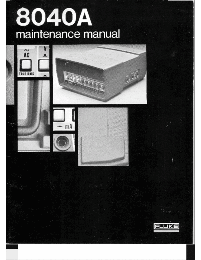
maintenance manual
John Fluke Mfg. Co., Inc. P.O. Box 43210 Mountlake Terrace, Washington 98043
/
/
Table of Contents
SECTION TITLE PAGE
1 INTRODUCTION AND SPECIFICATIONS ......................................... 1-1
1.1 . INTRODUCTION ...................................................... 1-1
1.6 . SPECIFICATIONS ..................................................... 1-2
OPERATING INSTRUCTIONS ................................................... 2-1
2.1 . INTRODUCTION ....................................................... 2-1
2.3 . SHIPPING INFORMATION ............................................. 2-1
2.6 . INPUTPOWER ........................................................ 2-1
2.8 . OPERATING FEATURES ......................... .....................
; 2-1
2.10 . OPERATING NOTES ................................................... 2-1
2- 12. Fuse Replacement ..................................................... 2-1
2- 14. Overrange Indication ........................................... 2-1
2.16 . Input Overload ~ r o t e c t l b i A .......................................... 2-1
2.18 . ASSEMBLY AND INITIAL OPERATION ................................. 2-3
2.22 . FUNCTION SELECTION EXAMPLES ................................... 2-5
THEORY OF OPERATION ........................................................ 3-1
3.1 . INTRODUCTION ...................................................... 3-1
3.3 . OVERALL FUNCTIONAL DESCRIPTION ............................... 3-1
3.4 . Introduction .......................................................... 3-1
3.6 . Analog Circuits ....................................................... 3-2
3.8 . Digital Circuits ........................................................ 3-2
3.10 . CIRCUIT DESCRIPTION ............................................... 3-2
3-1 1. Introduction .......................................................... 3-2
3.13 . Input Divider ......................................................... 3-2
3.15 . Current Shunts ........................................................ 3-2
3.17 . Buffer ............................................................... 3-2
3.19 . A/ D Reference ........................................................ 3-2
3.26 . Ohms Voltage Source .................................................. 3-5
3.28 . RMSConverter ....................................................... 3-5
3.33 . A/DConverter ....................................................... 3-5
3.35 . Timing and Control .................................................... 3-6
3.38 . Display .............................................................. 3-6
(Continued on next page)
SECTION TITLE PAGE
4 MAINTENANCE ................................................................. 4-1
4-1 . INTRODUCTION ...................................................... 4-1
4-4. GENERAL MAINTENANCE ............................................ 4-2 .
4-5 . Access Information .................................................... 4-2
4-7 . Cleaning ............................................................. 4-2
4-9 . Fuse Replacement ..................................................... 4-2
4-1 1. PERFORMANCE CHECK .............................................. 4-2
4-13 . DCVolts ............................................................. 4-3
4-15 . ACVolts ............................................................. 4-3
4-17 . Resistance Measurements ............................................... 4-3
4-19 . Directcurrent ........................................................ 4-3
4-2 1. Alternating Current .................................................... 4-3
4-23. CALIBRATION ........................................................ 4-5
4-26. ...........................
Required Method for Votlage Source Connection 4-5
4-29 . TROUBLESHOOTING ................................................. 4-8
5 LISTOFREPLACEABLEPARTS .................................................. 5-1
5.1 . INTRODUCTION ...................................................... 5-1
5.4 . HOW T O OBTAIN PARTS .............................................. 5-1
5.7 . USE CODE EFFECTIVITY LIST ......................................... 5-1
6 OPTIONS & ACCESSORY INFORMATION ........................................ 6-1
6.1 . INTRODUCTION ...................................................... 6-1
6.3 . RECHARGEABLE BATTERY PACK, 8040A.7005 .......................... 6-1
6.4 . Introduction ........................................................... 6-1
6.6 . Operation ............................................................ 6-1
6.8 . BATTERY COVER KIT, 8040A-7004 ...................................... 6-1
6.10 . BATTERY COVER, 8040A-7007 .......................................... 6-1
6.12 . CARRYING CASE (C88) ................................................ 6-1
6.14 . BATTERY CHARGER/ ELIMINATOR ................................... 6-3
6.16 . TEMPERATURE PROBE (80T-150) ...................................... 6-3
6- 17. Introduction .......................................................... 6-3
6.20 . OperatingNotes ....................................................... 6-3
6.25 . Operating Instructions................................................. 6-3
6.27 . DELUXE TEST LEAD KIT (A80) ......................................... 6-4
6.29 . CURRENT TRANSFORMER, CLAMP-ON (801-600) ....................... 6-4
6.30 . Introduction .......................................................... 6-4
6.32 . Operation ............................................................ 6-5
6.34 . HIGH VOLTAGE PROBE (80F-5) ........................................ 6-5
6.35 . Introduction .......................................................... 6-5
6.39 . Cleaning ............................................................. 6-5
6-4 1. Calibration ........................................................... 6-5
6.44 . HIGH VOLTAGE PROBE (80F-15) ....................................... 6-6
6.45 . Introduction .......................................................... 6-6
6.49 . Cleaning ............................................................. 6-6
6-5 1. Calibration ........................................................... 6-6 '
6.54 . HIGH VOLTAGE PROBE (80K-40) ....................................... 6-7
6.55 . Introduction .......................................................... 6-7
6.58 . HIGH FREQUENCY PROBE (81 RF) ...................................... 6-7
6.59 . Introduction .......................................................... 6-7
6.61 . HIGH FREQUENCY PROBE (82RF) ...................................... 6-7
6.62 . Introduction .......................................................... 6-7
7 SCHEMATIC DIAGRAM ......................................................... 7-1
List of Illustrations
.
FIGURE TITLE PAGE
Control. Indicator and Connector Locations ........................................... 2-2
Function Selection Examples ....................................................... 2-5
8040A Block Diagram ............................................................. 3-1
Simplified Buffer Circuit ........................................................... 3-3
Simplified A/ D Reference Circuit .................................................... 3-4
RMS Converter Representation ..................................................... 3-5
Simplified RMS Converter Circuit ................................................... 3-6
Dual-Slope A/ D Conversion Timing for VAC or VDC Inputs ............................ 3-7
Calibration Adjustment Controls .................................................... 4-4
Required Method for Voltage Source Connection ....................................... 4-5
Waveform at U26 Pin 8 for In Range and Overrange Inputs ............................... 4-9
Waveforms at TP1. Q10. C22 and U14 for In Range and Overrange Inputs.................. 4-10
Oscilloscope Connections for Troubleshooting ......................................... 4-11
MainPCBAssembly ............................................................... 5-4
Digital Conditioner PCB Assembly.................................................. 5-8
Analog Converter PCB Assembly .................................................... 5-10
8040AAccessories ................................................................. 6-2
..............
Initial CaseTemperature above Ambient versus Meter Reading above Ambient 6-4
Maximum R F Signal Limits (V RMS) at Probe Tip ..................................... 6-4
DeluxeTestLeadKit .............................................................. 6-4
801-600 Current Transformer ........................................................ 6-5
80F-5VoltageDivider ............................................................. 6-5
80F- 15 Voltage Divider ............................................................ 6-6
80K-40VoltageDivider ............................................................ 6-7
81RFHighFrequencyProbe ........................................................ 6-7
82RF High Frequency Probe ......................................................... 6-7
iii
List of Tables
TABLE TITLE PAGE
Accessories ...................................................................... 1. 1
Control. Indicator and Connector Description ......................................... 2-3
8040A Maximum Allowable Input Overload Conditions ................................. 2-4
Buffer Gain Configuration. kR Function .............................................. 3-2
Recommended Test Equipment ...................................................... 4-1
DCVoltage ...................................................................... 4-3
AC Voltage Performance Check ..................................................... 4-3
Resistance Performance Check ...................................................... 4-3
Direct Current Performance Check ................................................... 4-4
DC Voltage Calibration ............................................................ 4-6
Ohms Calibration ................................................................. 4-7
LowFrequencyACVCheck ........................................................ 4-8
HighFrequencyACVCheck ........................................................ 4-8
Direct Current Accuracy Check ...................................................... 4-8
Battery Charger/ Eliminator Input Power Configurations ................................ 6-3
8040A Ranges for Current Transformer (801-600) ....................................... 6-5
Section 1
Introduction & Specifications
1-1. INTRODUCTION ments are made using true rms conversion techniques for
improved accuracy in communications and industrial
1-2. The Model 8040A Multimeter provides the control applications.
accuracy and portability required in today's field service
work. A sunshade protects the 41/2 digit LED 1-4. Several accessories are available for use with the
display from glare when operating the 8040A in adverse
8040A to expand its' capabilities. A list of these
lighting conditions. The small size and battery power add
accessories is provided in Table 1-1 while more detail
to the portability; yet the fold-away stand allows the about each one is provided in Section 6.
instrument to be positioned at a convenient angle for
bench top use.
1-5. Note that two of the accessories, the 80T-150
1-3. The 8040A offers 20,000 count resolution in all temperature probe and A81 battery chargerleliminator,
five functions which provides measurement resolution to are configured a t the factory for particular applications.
0.01 ohms on the 200 ohm rangeand I0 microvolts on the Insure that the correct form of the model number is used
200 millivolt range. AC voltage and current measure- when ordering either of these accessories.
Table 1-1. ACCESSORIES
ACCESSORY DESCRIPTION ACCESSORY DESCRIPTION
801-600 Clamp-on current probe; 2 t o 600 amps 8040A- A rechargeable Ni-Cad battery pack
80F-5 High voltage probe; 5 kV 7005K (batteries come secured in the battery
cover)
8OF-15 High voltage probe; 15 kV
8040A- A battery cover intended for use with
80K-40 High voltage probe; 40 kV
7007 K alkaline batteries (batteries not included:
81 RF High frequency probe; 20 kHz to
A81-115 Battery chargerleliminator for 115V,
100 MHz
50 to 60 Hz line source
82R F High frequency probe; 100 kHz t o
A81-100 Battery charger/eliminator for IOOV,
500 MHz
50 t o 60 Hz line source
~OT-I~OC Temperature probe; - 5 0 ' ~ to +I 5 0 ' ~
~81-230-~ Battery chargerleliminator for 230V,
80T-150F -58' F to +302' F 50 to 60 Hz line source (U.S. type
C88 Carrying case plug)
A80 Deluxe test lead kit
A81-230 Battery chargerleliminator for 230V,
8040A- A battery cover kit; includes 4 "C" 50 to 60 Hz line source (European
7004K size alkaline batteries type plug)
1-6. SPECIFICATIONS
D C Voltage
Ranges: (Autorangingor Manual) .............. 31200 mV, *2V, f 2 0 V , f200V, f I IOOV
Accuracy: (6 months, 18" t o 28◦ Jabse Service Manual Search 2026 ◦ Jabse Pravopis ◦ onTap.bg ◦ Other service manual resources online : Fixya ◦ eServiceinfo