Service Manuals, User Guides, Schematic Diagrams or docs for : GM Car Audio CDX-M1026
<< Back | HomeMost service manuals and schematics are PDF files, so You will need Adobre Acrobat Reader to view : Acrobat Download Some of the files are DjVu format. Readers and resources available here : DjVu Resources
For the compressed files, most common are zip and rar. Please, extract files with Your favorite compression software ( WinZip, WinRAR ... ) before viewing. If a document has multiple parts, You should download all, before extracting.
Good luck. Repair on Your own risk. Make sure You know what You are doing.
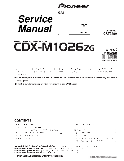
Image preview - the first page of the document

>> Download CDX-M1026 documenatation <<
Text preview - extract from the document
                                                                     GM

      Service
      Manual                                                                                                                                    ORDER NO.
                                                                                                                                            CRT2290

MULTI-COMPACT DISC PLAYER


CDX-M1026ZG                                                                                                                                      X1H/UC


 VEHICLE                    DESTINATION                  PRODUCED AFTER        GM PART No.                    ID No.         PIONEER MODEL No.
 Oldsmobile,                U.S.A., CANADA               February 1999         25659167                                      CDX-M1026ZG/X1H/UC
 Buick, Pontiac
- See the separate manual CX-653(CRT1916) for the CD mechanism description, disassembly and circuit
   description.
- The CD mechanism employed in this model is one of C6 series.


CONTENTS
 1.   SAFETY INFORMATION ............................................3         7. GENERAL INFORMATION .......................................39
 2.   EXPLODED VIEWS AND PARTS LIST .......................4                      7.1 IC .........................................................................39
 3.   BLOCK DIAGRAM AND SCHEMATIC DIAGRAM .....9                                  7.2 DIAGNOSIS ........................................................41
 4.   PCB CONNECTION DIAGRAM ................................22                      7.2.1 DISASSEMBLY............................................41
 5.   ELECTRICAL PARTS LIST ........................................28               7.2.2 TEST MODE ................................................43
 6.   ADJUSTMENT..........................................................31         7.2.3 CONNECTOR FUNCTION DESCRIPTION..44
                                                                               8. OPERATIONS AND SPECIFICATIONS.....................45


PIONEER ELECTRONIC CORPORATION                   4-1, Meguro 1-Chome, Meguro-ku, Tokyo 153-8654, Japan
PIONEER ELECTRONICS SERVICE INC. P.O.Box 1760, Long Beach, CA 90801-1760 U.S.A.
PIONEER ELECTRONIC [EUROPE] N.V. Haven 1087 Keetberglaan 1, 9120 Melsele, Belgium
PIONEER ELECTRONICS ASIACENTRE PTE.LTD. 253 Alexandra Road, #04-01, Singapore 159936

C PIONEER ELECTRONIC CORPORATION 1999                                                                               K-ZZD. FEB. 1999 Printed in Japan
CDX-M1026ZG


- CD Player Service Precautions
1. For pickup unit(Service)(CXX1235) handling, please         2. During disassembly, be sure to turn the power off
   refer to"Disassembly"(see page 42).                           since an internal IC might be destroyed when a con-
   During replacement, handling precautions shall be             nector is plugged or unplugged.
   taken to prevent an electrostatic discharge(protection     3. Please checking the grating after changing the pickup
   by a short pin).                                              unit(see page 33) since these screws protects the
                                                                 mechanism during transport, be sure to affix it when
                                                                 it is transported for repair, etc.
- Transportation of multi-CD player


                                                       Transport screw
                                                       Attach to original position before transporting the set


                                                Seal
                                                After removing transport screw, cover the hole
                                                with the supplied.seal.


A transport screw has been attached to the set in order to protect it
during transportation. After removing the transport screw, cover the
hole with the supplied seal.Be sure to remove the transport screw
before mounting the set. The removed transport screw should be
retained in the accessory bag for use the next time the set is trans-
ported.


2
                                                                                                 CDX-M1026ZG


1. SAFETY INFORMATION
This service manual is intended for qualified service technicians; it is not meant for the casual do-it-yourselfer.
Qualified technicians have the necessary test equipment and tools, and have been trained to properly and safely repair
complex products such as those covered by this manual.
Improperly performed repairs can adversely affect the safety and reliability of the product and may void the warranty.
If you are not qualified to perform the repair of this product properly and safely; you should not risk trying to do so
and refer the repair to a qualified service technician.


                                                                                                                     3
CDX-M1026ZG


2. EXPLODED VIEWS AND PARTS LIST
2.1 EXTERIOR


4
                                                                                                CDX-M1026ZG


NOTE:
- Parts marked by "*" are generally unavailable because they are not in our Master Spare Parts List.
- Screws adjacent to  mark on the product are used for disassembly.

- EXTERIOR SECTION PARTS LIST

Mark No.     Description            Part No.                  Mark No.    Description             Part No.
       1     Screw                  BMZ20P040FMC                    31    Plug(CN1801)            CKS1049
       2     Screw                  BMZ26P040FMC                    32    Plug(CN1802)            CKS1050
       3     Screw                  BMZ30P040FMC                *   33    Plug(CN1702)            CKS1052
       4     Screw                  BMZ30P040FZK                    34    Connector(CN1701)       CKS2233
       5     Screw                  CBA1014                         35    Connector(CN1102)       CKS2398

         6   Screw                  CBA1037                          36   Holder                  CNC6672
         7   Screw                  CBA1353                          37   Holder                  CNC6784
         8   Spring                 CBH1862                          38   Screw                   BPZ20P060FMC
         9   Spring                 CBH2171                          39   Screw                   BPZ26P080FMC
        10   Connector              CDE5205                          40   Leaf Spring             CBL1286

        11   Transistor(Q1952)      2SB1335A                         41   Cord Assy               CDE5107
        12   Upper Case             CNB2096                          42   Clamper                 CEF1020
        13   Spacer                 CNC5536                          43   Lighting Conductor      CNV4720
        14   Bracket                CNC6782                          44   Grille Unit             CXA9439
        15   Holder                 CNC7211                          45   Screw                   IMS20P035FZK

        16   Holder                 CNC7213                          46 Screw                     IMS26P040FMC
        17   Seal                   CNM4918                          47 Screw                     IMS30P040FMC
        18   Insulator              CNM4973                          48 Screw                     IMS30P060FZK
        19   PCB                    CNP4402
        20   Grille                 CNS4146

        21   Cover                  CNS4153
        22   Damper                 CNV4502
        23   Arm Unit               CXA8606
        24   Lower Case Unit        CXA9466
        25   Bracket Unit           CXB1636

  *     26   Caution Card           HRP1090
        27   Polyethylene Bag       HEG0018
        28   CD Mechanism Module    CXK4551
        29   Extension Unit         HWX2034
        30   Screw                  BMZ26P050FMC


                                                                                                                 5
CDX-M1026ZG


2.2 CD MECHANISM MODULE


6
                                                                                     CDX-M1026ZG


- CD MECHANISM MODULE SECTION PARTS LIST


Mark No.   Description            Part No.       Mark No.   Description                  Part No.
       1   Screw                  CBA1369              46   Arm                          CNC6799
       2   CD Core Unit           CWX2014          *   47   Holder                       CNC6819
       3   Connector(CN701)       CKS1968          *   48   Holder                       CNC6827
       4   Connector(CN801)       CKS3484              49   Spacer                       CNM4879
       5   Connector(CN101)       CKS3486              50   Sheet                        CNM5118

       6   Pickup Unit(Service)   CXX1235          *   51   Sheet                        CNM5020
       7   Screw                  IMS26P040FMC         52   PCB                          CNP4205
       8   Screw                  JFZ17P020FNI     *   53   Spring                       CBL1304
       9   Screw(M2
◦ Jabse Service Manual Search 2024 ◦ Jabse Pravopis ◦ onTap.bg ◦ Other service manual resources online : Fixya ◦ eServiceinfo