Service Manuals, User Guides, Schematic Diagrams or docs for : General Electric 31-21456 GE RANGE

<< Back | Home

Most service manuals and schematics are PDF files, so You will need Adobre Acrobat Reader to view : Acrobat Download Some of the files are DjVu format. Readers and resources available here : DjVu Resources
For the compressed files, most common are zip and rar. Please, extract files with Your favorite compression software ( WinZip, WinRAR ... ) before viewing. If a document has multiple parts, You should download all, before extracting.
Good luck. Repair on Your own risk. Make sure You know what You are doing.


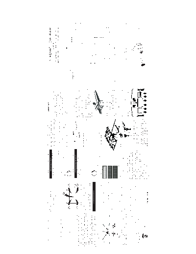
Image preview - the first page of the document
31-21456 GE RANGE


>> Download 31-21456 GE RANGE documenatation <<

Text preview - extract from the document
              IMPORTANT SAFETY NOTICE                                               NOTE: The orifices have spring loaded retaining                               BURNER OUTPUT RATINGS; BTU/HR                            LOW FLAME (SIMMER) ADJUSTMENT
                                                                                                                                                                                                                                                                                       183D8077G179
T H I S I N F O R M AT I O N I S I N T E N T E D F O R U S E B Y P E R S O N S
POSSESSING ADEQUATE BACKGROUNDS OF ELECTRICAL,
                                                                                    rings around the hex head to hold the orifice in
                                                                                    the nutdriver during installation and removal.                                           Natural Gas, 5" W.C.P
                                                                                                                                                                                                                          The top burner valves have low flame/simmer
                                                                                                                                                                                                                          adjustment screws in the center of the control                                                                                                                                             SCHEMATIC DIAGRAM
ELECTRONIC AND MECHANICAL EXPERIENCE. ANY ATTEMPT TO                                A slight amount of force is required to push the                          BURNER            BTU RATE                ORIFICE SIZE      valve shafts. A flashlight may be required to
R E PA I R A M A J O R A P P L I A N C E M AY R E S U LT I N P E R S O N A L
INJURY AND PROPERTY DAMAGE. THE MANUFACTURER OR
                                                                                    nutdriver down over the ring.
                                                                                                                                                                 RF              17,000                0.0783" (1.98mm)
                                                                                                                                                                                                                          locate the screw. A thin, flat bladed screwdriver
                                                                                                                                                                                                                                                                               REPLACING ORIFICE HOLDER AND TUBING                                                                                                          WARNING
                                                                                    d) Install the LP orifice spuds into their correct                                                                                    (approx. 3/32 across) is needed to access the        The Orifice Holder and Supply Tubing are one
SELLER CANNOT BE RESPONSIBLE FOR THE INTERPRETATION                                                                                                              LF               12,000               0.064" (1.62mm)
                                                                                                                                                                                                                          screw.                                               assembly. To replace the assembly:                                                                                                 POWER MUST BE DISCONNECTED
OF THIS INFORMATION, NOR CAN IT ASSUME ANY LIABILITY IN                             positions as described as follows.
CONNECTION WITH ITS USE.                                                                                                                                         LR                9,500            0.0555" (1.41mm)                                                             Follow the instructions under "Raise or Remove                                                                                  BEFORE SERVICING THIS APPLIANCE
                                                                                                                                                                 RR                5,000            0.0409" (1.04mm)       To Adjust The Low Flame Setting-At least 2            cooktop" (column 4).
                                                                                                                                                                                                                                                                                                                                                                                                                                                                                      COM         NO           O
          DISCONNECT POWER BEFORE SERVICING                                                                           LP- Orange /
                                                                                                                                                              CENTER              10,000             0.058" (1.473mm)      other surface burners must be lit. Then, lite the     Remove the 3/4" nut securing the orifice holder                                                                                                                                                 Y
               IMPORTANT-RECONNECT ALL                                                                                    Green
                                                                                                                                                                                                                           burner being adjusted and turn knob to "LOW".         being replaced to the bracket. Use a 3/4" open                                                                                                                                    LATCH
                                                                                                                                                                                                                                                                                                                                                                                                                                                                  SWITCH
                                                                                                                                                                                                                                                                                                                                                                                                                                                                                      COM         NO           S

                  GROUNDING DEVICES.                                                                                                                           BAKE               16,000                 #49 (.073")                                                             ended or adjustable wrench to loosen the nut.
                                                                                                                                                                                                                           Remove knob and insert the screwdriver into                                                                                                                                                                                                                               Y
                                                                                                                                                                                                                                                                                                                                                                                                                                                                                                                                         NOTES:
                                                                                                                                                               BROIL              13,500                 #51 (.067")       valve shaft. Turn the adjustment screw until the      Loosen the 1/2" nut securing the tubing to the                                                                                                                                              M1
                                                                                                                                                                                                                                                                                                                                                                                                                                                                                          W
ALL PARTS OF THIS APPLIANCE CAPABLE OF CONDUCTING                                                                                                                                                                                                                                                                                                                                                                                                       OVEN                                                                             1. WARNING: POWER MUST BE DISCONNECTED BEFORE

ELECTRICAL CURRENT ARE GROUNDED. IF GROUNDING WIRES,                                  LP- Blue /                                          LP- Blue /                                                                       flame reaches the desired size.                       valve.                                                                                                                                                                SENSOR                M2
                                                                                                                                                                                                                                                                                                                                                                                                                                                                                          S
                                                                                                                                                                                                                                                                                                                                                                                                                                                                                                                                           SERVICING THE APPLIANCE.
                                                                                          Brown                                               Blue                162              Denotes 1.62mm Orifice size opening
                                                                                                                                                                                                                                                                                                                                                        POWER SUPPLY
SCREWS, STRAPS, NUTS OR WASHERS USED TO COMPLETE A                                                                                                                                                                                                                                                                                                                                               TOROID
                                                                                                                                                                                                                                                                                                                                                                                                                                            AT 75


◦ Jabse Service Manual Search 2024 ◦ Jabse PravopisonTap.bg ◦ Other service manual resources online : FixyaeServiceinfo