Service Manuals, User Guides, Schematic Diagrams or docs for : Gould Gould Advance DSO400u
<< Back | HomeMost service manuals and schematics are PDF files, so You will need Adobre Acrobat Reader to view : Acrobat Download Some of the files are DjVu format. Readers and resources available here : DjVu Resources
For the compressed files, most common are zip and rar. Please, extract files with Your favorite compression software ( WinZip, WinRAR ... ) before viewing. If a document has multiple parts, You should download all, before extracting.
Good luck. Repair on Your own risk. Make sure You know what You are doing.
Image preview - the first page of the document
>> Download DSO400u documenatation <<
Text preview - extract from the document
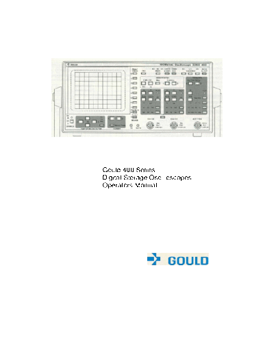
Gould 400 Series
Digital Storage Oscilloscopes
Operators Manual
Gould 400 Series
Digital Storage Oscilloscopes
Operators Manual
Copyright@1990 Gould lnc., Instruments Division
(Gould Electronics Ltd.)
400 Operators Manual
Contents
Introduction
Getting Started 1
Advanced Features 2
The Menus 3
Performance Checking 4
Waveform Processing 5
Battery Unit Operation 6
Alphabetical Summary 7
Appendix 1 Error Messages A1
Appendix 2 Specification A2
Appendix 3 Remote
Operation A3
Appendix 4 Front & Back
Pictures
I Service Facilities
Contents 400 Operators Manual
Introduction 2.5 Plot
2.5.1 Internal Colour Plotter
1. Getting Started 2.5.2 Pens ti
O
1.1 Safety and Power Requirements 2.5.3 Pen Changing
1.1.1 International Safety Warning 2.5.4 Paper Selection
1.1.2 Grounding 2.5.5 Paper Loading
1.1.3 Live Parts 2.5.6 Internal plotting
1.1.4 Ventilation and Dust 2.5.7 External plots
1.1.5 Operating Temperatures 2.5.8 Plot positioning and scaling
1.1.6 Power & Frequency
Requirements 2.6 Data Transfer
1.1.7 Fuse Requirements 2.6.1 Syntax
2.6.2 Receiving Data
1.2 Using the Buttons 2.6.3 Error Status
1.3 Start-Up Display
1.4 Obtaining a Trace 2.7 Real Time Clock
1.4.1 AUTO SETUP
1.4.2 Channel Selection (Off/On/lnv) 3. The Menus
1.4.3 Coupling (AC/DC/Gnd) 3.1 Additional Buttons
3.1.1 The Numeric Buttons
1.5 Horizontal Adjustments 3.1.2 Menu Traces
1.5.1 TIME/DIVISION 3.1.3 Control
1.5.2 Aliases 3.1.4 Post Store
1.5.3 Position
1.5.4 Magnification 3.2 Control Master Menu
3.3 Status Menu
1.6 Vertical Adjustments 3.3.1 Mode
1.6.1 VOLTS/DIVISION 3.3.2 Max/Min
1.6.2 Position 3.3.3 V/Div
1.6.3 Variable/Uncalibrated 3.3.4 Probe set
1.6.4 Add 3.3.5 Timebase
3.3.6 Trigger
1.7 Manually Obtaining a Trace
1.8 Operating Hints 3.4 Display and Trigger Menu
1.8.1 Intensities too low 3.4.1 Probe ratio
1.8.2 Trace off the top or bottom 3.4.2 Max/Min
of screen 3.4.3 Dot Join
1.8.3 Trace not being acquired 3.4.4 Averaging
1.8.4 Trace unstable 3.4.5 Trig Pos'n
1.8.5 Trace has flat top or bottom
3.5 Display Intensity
2. Advanced Features 3.6 Reference Trace
2.1 Trigger Control 3.7 RS423 Interface Menu
2.1.1 Selecting Source and Coupling 3.7.1 RS423 Plot Connections
2.1.2 Level 3.7.2 RS423 Data Connections
2.1.3 Trigger Point (T)
2.1.4 Slope (+/-) 3.8 Special Functions Menu
2.1.5 Trigger Mode (Norm/Auto) 3.9 Post Store Master Menu
2.1.6 Trigger Delay 3.10 Save Trace Menu
3.11 Recall Memory Menu
2.2 Capture Facilities 3.12 Plot Menu
2.2.1 Trace Hold
2.2.2 S/Shot and Run 4. Performance checking
2.2.3 Acquisition Status-AFTS 4.1 Risetime
4.2 Bandwidth
2.3 Display Modes 4.3 Trigger sensitivity
2.4 Cursor Measurements 4.4 Trigger bandwidth
2.4.1 Cursor and Datum Selection 4.5 Timebase calibration
2.4.2 The Cursor& Datum Lines 4.6 Vertical Calibration
2.4.3 Making Measurements 4.7 Max-Min (Alias Detector)
400 Series Operators Manual Contents
5. Waveform Processing Functions Figure List
5.1 Cursor Measurements 1.2a Single Function Buttons
5.1.1 Voltage and Time 1.2b The Toggles
5.1.2 Peak-Peak 1.2c Pressure Sensitive Buttons
5.1.3 Max-Min 1.3 Start-Up Display
5.1.4 Risetime (falltime) 1.4 Obtaining a trace
5.1.5 Overshoot (preshoot) 1.4.1 An AUTO SETUP Display
5.1.6 Pulse Width 1.5 Horizontal Controls
5.1.7 Frequency, Period, Duty Cycle 1.5.2 Alias Generation
5.1.8 RMS 1.6 Vertical Controls
5.1.9 Area 2.1 Trigger Controls
2.1.6 Trace Capture with Delay
5.2 Trace Manipulation 2.2 Capture Controls
5.2.1 Filter Frequency 2.4 The Cursor and Datum Line Controls
5.2.2 Filter Current Trace 2.4.2 The Cursor and Datum Lines
5.2.3 Invert Current Trace 2.5.5 Paper Loading
5.2.4 Integrate Signal 2.5.8a Relative Plot Positions
5.2.5 Integrate Current Trace 2.5.8b Plot Dimensions
3 Menu Overview
5.3 Trace arithmetic 3.1 Numeric Buttons
3.2 Control Master Menu
5.4 Persistence/Limits Testing 3.3 A Status Menu
5.4.1 Limits 3.4 A Display and Trigger Menu
5.4.2 Persistence 3.5 Display Intensity Menu
3.6 Reference Trace Menu
6. Battery Unit Operation 3.7 An RS423 Interface Menu
3.7.1 400to Gould 6120 or HP7475 Connections
7. Alphabetical Summary of controls 3.7.2a 400 to IBM-PC/XT Connections
3.7.2b 400 to IBM-PC/AT Connections
Appendix 1: Error Messages 3.8 Special Functions Menu
3.9 Post Storage Master Menu
Appendix 2: Specification 3.10 Save Trace Menu
3.11 Recall Trace Menu
Appendix 3: Remote DC operation of the DSO 3.12 Plot Menu
5.1a Cursor Measurements Menu
Appendix 4: Front and Back Pictures 5.1b Example of Calculations on trace
5.1.1 Voltage and Time Measurement
Service Facilities 5.1.2 Peak to Peak Measurement
5.1.3 Max-Min Measurement
5.1.4 Risetime Measurement
5.1.5 Overshoot Measurement
5.1.6 Pulse Width Measurement
5.1.7 Freq. Period and Duty Cycle Measurement
5.1.9 Area Measurement
5.2 Trace Manipulation Menu
5.4 Persistence/Limits Testing Menu
6 Battery Unit Interconnections
6.2 Battery Unit Front Panel Indicators
A2 400 Series Dimensions
A3.2 DC Power Connections
A4a Rear View
A4b RS423 Connections
A4c Front Panel Controls
400 Operators Manual Introduction
Introduction
The Gould 400 series instruments are Digital Storage More advanced features of the 400 series include a com-
Oscilloscopes (DSOs). They include all the features prehensive range of menu-controlled functions. For
expected of advanced modern oscilloscopes designed for example, the Display and Trigger menu operates features
the professional engineer, whilst retaining the user- such as the trigger delay and pre-trigger display
friendliness essential for those learning to use such functions. The pre-trigger display function allows the
instruments for the first time. signal prior to the trigger point to be captured and
The 400 range consists of three basic models; the 400 the displayed.
420 and the 450. All versions can be fitted with a battery Three complete traces can be stored for future use and
unit which provides the instrument with a fully automatic recalled to the display via the Save Trace and Recall
built in Nickel Cadmium battery and charger which Trace menus respectively. With the built in battery back
allows uninterrupted operation of the DSO in the event up facility, these will be retained even when the
of an AC supply failure and complete operation instrument is switched off.
independent of an AC supply. In addition to the above features, the 420 and 450 instru-
Obtaining a trace is especially simple - just connect the ments have a built in 4 colour plotter and a battery
signal and press the Auto Setup button - the 400 does the backed Real Time Clock. This provides a simple and
rest. Having obtained a trace, readily accessible datum convenient method of obtaining permanent hard copy
lines and a cursor make it easy to take automatic timing plots of the screen display. The plots will contain the date
and voltage measurements directly from the display. On and time of acquisition together with the date and time of
the 420 and 450 models, the waveform processing plotting.
function increases the power of the cursor measurements The 450 has all the features of the 420 and has a signal
in terms of both capture and post storage analysis and bandwidth of 50MHz and an extra timebase range of
measurement functions. 50ns/div.
The innovative use of ergonomically designed pressure
sensitive push button controls provides a combination of
precision and flexibility for ease of operation.
Numbers circled in the text refer to the controls shown
on the front panel picture in Appendix 3.
Getting Started 1.1-1.1.6 400 Series Operators Manual
1.1 Safety and Power Requirements they should be removed only by suitably qualified personnel
for maintenance and repair purposes.
1.1.1 International Safety Warning
(as required for I.E.C. 348 Cat I) WARNING: Removing the covers may expose voltages in
This instrument has been designed and tested in accordance excess of 8000V at the side of the display tube; these
with IEC publication 348, and has been supplied in a safe may be present for up to one minute after the
condition. This manual contains information and warnings instrument has been disconnected from the power
which must be observed to keep the instrument in a safe source.
condition. The instrument should not be switched on if it is
damaged and it should not be used under wet conditions. 1.1.4 Ventilation and Dust
For the correct and safe use of this instrument it is essential that
The instrument relies on forced air cooling via a fan and
both operating and service personnel follow generally accepted
ventilation slots. Adequate ventilation can usually be achieved
safety procedures in addition to the safety precautions specified
by leaving a 75mm (3" gap) around the instrument.
in this manual.
The instrument should not be operated in dusty environments.
Whenever it is likely that safety-protection has been impaired,
the instrument must be made inoperative and be secured against If the CRT filter requires cleaning it can be easily removed by
any unintended operation. Qualified maintenance or repair pressing in its right hand edge as shown by the moulded arrow.
personnel should be informed. Safety protection is likely to be
impaired if, for example the instrument shows visible damage
or fails to perform the intended measurements correctly.
1.1.5 Operating Temperatures
1.1.2 Grounding
The instrument is designed to be operated in an environment
THE INSTRUMENT MUST BE GROUNDED. having an ambient temperature of between 0 and 50 degrees C,
AC (0 to 45 degrees if the battery unit is fitted) and to operate with
The instrument must be operated with a protective ground full accuracy between 15 and 35 degrees C.
connected via the yellow/green conductor of the supply cable. Note: Direct sunlight, radiators and other heat sources
This is connected to the instrument before the line and neutral should be taken into account when assessing the ambient
connections when the supply plug is inserted into the socket on temperature.
the back of the instrument. If the final connection to the supply
is made elsewhere, ensure that the ground connection is made The instrument may occasionally be subjected to temperatures
before line and neutral. between 0 and -10◦ Jabse Service Manual Search 2026 ◦ Jabse Pravopis ◦ onTap.bg ◦ Other service manual resources online : Fixya ◦ eServiceinfo