Service Manuals, User Guides, Schematic Diagrams or docs for : Grundig CUC CUC-400 CUC-400

<< Back | Home

Most service manuals and schematics are PDF files, so You will need Adobre Acrobat Reader to view : Acrobat Download Some of the files are DjVu format. Readers and resources available here : DjVu Resources
For the compressed files, most common are zip and rar. Please, extract files with Your favorite compression software ( WinZip, WinRAR ... ) before viewing. If a document has multiple parts, You should download all, before extracting.
Good luck. Repair on Your own risk. Make sure You know what You are doing.


Image preview - the first page of the document
CUC-400


>> Download CUC-400 documenatation <<

Text preview - extract from the document
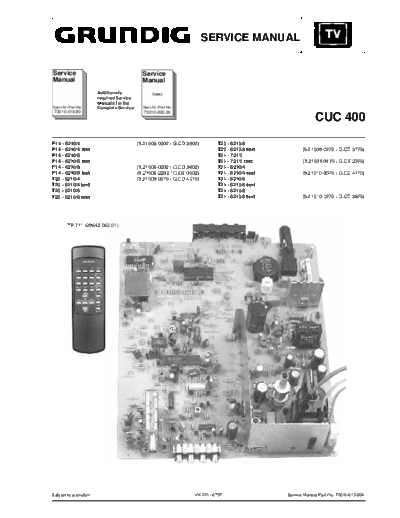
                                                                         SERVICE MANUAL


Service                                       Service
Manual                                        Manual
                        Additionally               Safety
                        required Service
                        Manuals for the
Sach-Nr./Part No.       Complete Service:     Sach-Nr./Part No.
 72010-019.80                                  72010-800.00
                                                                                                               CUC 400
P14 - 6210/4                                (9.21508-0302 / G.CD 3902)        T20 - 6210/8
P14 - 6210/4 text                                                             T20 - 6210/8 text          (9.21509-0275 / G.CD 3775)
P14 - 6210/6                                                                  T51 - 721/5
P14 - 6210/6 text                                                             T51 - 721/5 text           (9.21509-0475 / G.CE 2375)
P14 - 6210/8                                (9.21508-0202 / G.CD 3602)        T21 - 6210/4
P14 - 6210/8 text                           (9.21508-2202 / G.CE 0502)        T21 - 6210/4 text          (9.21510-0375 / G.CD 4175)
T20 - 6210/4                                (9.21509-0375 / G.CD 4075)        T21 - 6210/6
T20 - 6210/4 text                                                             T21 - 6210/6 text
T20 - 6210/6                                                                  T21 - 6210/8
T20 - 6210/6 text                                                             T21 - 6210/8 text          (9.21510-0275 / G.CD 3875)


        TP 711 (29642-062.01)


Subject to alteration                                               VK 221 / 0797                 Service Manual Part No. 72010-019.80A
General Section                                                                                                                                                 CUC 400


Table of Contents

                                                                                          Page
                                                                                                                   25Hz interlace signal
General Section .................................... 1-2...1-7                                        25Hz
Safety Advice ...............................................................................   1-2                Volume
Circuit Diagram Symbols .............................................................           1-2
Technical Data .............................................................................    1-3                Tint
Operating Instructions ..................................................................       1-4
                                                                                                                   Brightness
Alignments ..................................................... 2-1                                               Contrast
Layout of the PCBs                                                                                                 Colour contrast
and Circuit Diagrams ........................... 3-1...3-7                                                         Automatic gain control
Oscillograms Chassis Board ........................................................             3-1   AGC
General Circuit Diagram ..............................................................          3-2                Audio signal
                                                                                                      AUDIO
Chassis Board PCB .....................................................................         3-5
CTR Panel PCB ...........................................................................       3-7   AUDIO        Audio signal input
                                                                                                        IN

Spare Parts List .................................... 4-1...4-5                                       AUDIO
                                                                                                       OUT
                                                                                                                   Audio signal output

                                                                                                                   Blue signal
                                                                                                          B
General Section                                                                                           BB       Baseband

                                                                                                                   Coincidence
                                                                                                      COIN
                                                                                                                   CCVS signal
                                                                                                      FBAS
                                                                                                                   Green signal
                                                                                                          G
                                                                                                       HOR.        Horizontal synchronizing pulse
                                                                                                      SYNC1
    The regulations and safety instructions shall be valid as provided                                             Intermediate frequency
    by the "Safety" Service Manual, part number 72010-800.00, as                                          IF
    well as the respective national deviations.                                                                    Red signal
                                                                                                          R
                                                                                                                   Beam current limiting
                                                                                                          SB
                                                                                                                   I2C-Bus Clock
                                                                                                      SCL
 Safety Advice                                                                                                     I2C-Bus data
                                                                                                      SDA
 The X-radiation developing in the sets conforms to the X-radiation                                   SOUND        Sound intermediate frequency
                                                                                                        IF
 Regulations (January 8, 1987), issued by the Physikalisch-Technische
 Bundesanstalt (federal physiotechnical institution).                                                  VERT.       Vertical synchronizing pulse
                                                                                                       SYNC
 The high tension for the picture tube and thus the developing X-
                                                                                                      VIDEO        Video signal
 radiation depends on the precise adjustment of the +A power supply.
 After every repair of the power supply unit or the horizontal deflection                             VIDEO        Video signal input
 stage it is imperative that the EHT for the picture tube is checked and                                IN
 re-adjusted if necessary.                                                                            VIDEO        Video signal output
 To avoid consequential damages to the chassis or the picture tube                                     OUT

 the integrated protective circuits are allowed to be put out of operation                            U            Switching voltage AV
                                                                                                          AV
 only for a short time.
                                                                                                      U
                                                                                                                   Switching voltage data mode
 When replacing the picture tube use only the types specified in the                                       DATA

 spare parts lists.                                                                                                Switching voltage norm
                                                                                                      U
                                                                                                          NORM

                                                                                                      U            Switching voltage standby
                                                                                                          STBY

                                                                                                      U            UHF switching voltage
                                                                                                          UHF

                                                                                                      U            Automatic frequency control voltage
                                                                                                            AFC
Circuit Diagram Symbols                                                                               U            Voltage synthesizer tuning
                                                                                                            TUN.
                                                                                                      TUN          Tuning voltage
                                                                                                            ADJ.
               Vertical amplitude                                                                                  Delayed control voltage
                                                                                                      U

                                                                                                      U            Switching voltage VHF high band
                                                                                                          VH
               Horizontal amplitude
                                                                                                      U            Switching voltage VHF low band
                                                                                                          VL


               Horizontal picture position


               Vertical picture position


               Vertical linearity


1-2                                                                                                                                                      GRUNDIG Service
GRUNDIG Service


                                                                                                                                                                                                                                                                                            Technical Data

                                                                                                                                                                                                                                                                                                             CUC 400
                                                 P14-6210/4              P14-6210/6              P14-6210/8              T20-6210/4              T20-6210/6              T20-6210/8              T 51-721/5             T21-6210/4              T21-6210/6              T21-6210/8
                                               P14-6210/4 text         P14-6210/6 text         P14-6210/8 text         T20-6210/4 text         T20-6210/6 text         T20-6210/8 text         T 51-721/5 text        T21-6210/4 text         T21-6210/6 text         T21-6210/8 text


                  Picture Tube

                  Visible picture                    34cm                    34cm                    34cm                    48cm                    48cm                    48cm                   48cm                    51cm                    51cm                    51cm


                  Screen diagonale                37cm (14")              37cm (14")              37cm (14")              51cm (20")              51cm (20")              51cm (20")             51cm (20")              55cm (21")              55cm (21")              55cm (21")


                  Deflection angle                    90


◦ Jabse Service Manual Search 2024 ◦ Jabse PravopisonTap.bg ◦ Other service manual resources online : FixyaeServiceinfo