Service Manuals, User Guides, Schematic Diagrams or docs for : Hyundai TV H-TV2506PF-2906PF H-TV2506PF-2906PF 25_29_Chassis_M113 M113_Service_Manual
<< Back | HomeMost service manuals and schematics are PDF files, so You will need Adobre Acrobat Reader to view : Acrobat Download Some of the files are DjVu format. Readers and resources available here : DjVu Resources
For the compressed files, most common are zip and rar. Please, extract files with Your favorite compression software ( WinZip, WinRAR ... ) before viewing. If a document has multiple parts, You should download all, before extracting.
Good luck. Repair on Your own risk. Make sure You know what You are doing.
Image preview - the first page of the document
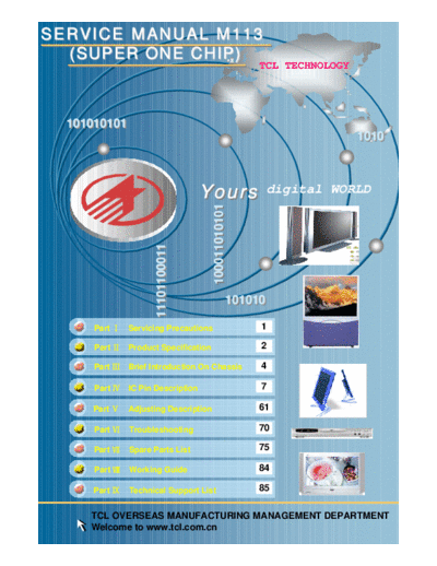
>> Download M113_Service_Manual documenatation <<
Text preview - extract from the document
SERVICE MANUAL M113
  (SUPER ONE CHIP)
                                                     TCL TECHNOLOGY


  101010101
  101010101
                                                                      1010
                                                                      1010


                                   Yours
                                      100011010101
                                                      digital WORLD
                     11101100011
                     11101100011


                                                101010
                                                101010

      Part Servicing Precautions                     1

      Part Product Specification                     2

      Part Brief Introduction On Chassis             4

      Part IC Pin Description                        7

     Part     Adjusting Description                  61

      Part    Troubleshooting                        70

      Part    Spare Parts List                       75

      Part    Working Guide                          84

      Part    Technical Support List                 85


     TCL OVERSEAS MANUFACTURING MANAGEMENT DEPARTMENT
     Welcome to www.tcl.com.cn
       SERVICE MANUAL
M113 (SUPER ONE-CHIP CHASSIS)


   Consultants:

   Guanghui Yu    Sansui Zhang
   Dongju Wu      Duncan Zhai

   Editors

   Lexus Sun    Bin Wu
   Guobiao Chen Alice Peng
TCL                                                                        M113 Chassis Service Manual

SERVICE MANUAL FOR M113 CHASSIS
PART I. Servicing Precautions
When working, the unit is with ultra high voltage about 25KV inside. So, to avoid the risk of electric shock,
be careful to adjust the chassis!


1. Only qualified personnel should perform service procedures.


2. All specification must be met over line voltage ranger of 110V AC to 240V AC 50Hz/60Hz.


3. Do not operate in WET/DAMP conditions.


4. Portions of the power supply board are hot ground. The remaining boards are cold ground.


5. Discharge of CRT anode should be done only to CRT ground strap.


6. When fuse blow, ensure to replace a fuse with the same type and specification.


7. Keep the wires away from the components with high temperature or high voltage.


8. When replacing the resister with high power, keep it over the PCB about 10mm.


9. The CRT anode high voltage has been adjusted and set in the factory. When repairing the chassis, do
not make the high voltage exceed 27.5KV (The beam current is 0uA). Generally, the high voltage is set on
25.5KV
◦ Jabse Service Manual Search 2026 ◦ Jabse Pravopis ◦ onTap.bg ◦ Other service manual resources online : Fixya ◦ eServiceinfo