Service Manuals, User Guides, Schematic Diagrams or docs for : HP Publikacje 5964-3586E
<< Back | HomeMost service manuals and schematics are PDF files, so You will need Adobre Acrobat Reader to view : Acrobat Download Some of the files are DjVu format. Readers and resources available here : DjVu Resources
For the compressed files, most common are zip and rar. Please, extract files with Your favorite compression software ( WinZip, WinRAR ... ) before viewing. If a document has multiple parts, You should download all, before extracting.
Good luck. Repair on Your own risk. Make sure You know what You are doing.
Image preview - the first page of the document
>> Download 5964-3586E documenatation <<
Text preview - extract from the document
                                          Agilent PN 89400-13
                                          Extending Vector Signal Analysis to 26.5 GHz
                                          with 20 MHz Information Bandwidth
                                          Product Note


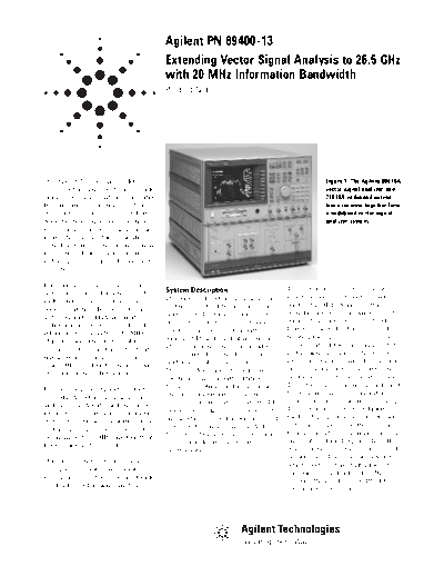
The Agilent Technologies 89400                                                                    Figure 1. The Agilent 89410A
series vector signal analyzers provide                                                            vector signal analyzer and
unmatched signal analysis capabilities                                                            71910A wideband surveil-
from traditional spectrum analysis to                                                             lance receiver together form
transient analysis, analog and digital                                                            a wideband vector signal
demodulation, high-speed spectrum                                                                 analyzer system.
monitoring, phase noise analysis, and
more. They are used in applications
as wide ranging as surveillance, signal
monitoring, digital communications,
radar signal analysis, and underwater
acoustics.

For some applications, the vector
                                          System Description                         The vector signal analyzer has two
signal analyzer's information band-
                                          The wideband vector signal analyzer        input channels, each with a band-
width and frequency coverage has
                                          system consists of two major compo-        width of 10 MHz. Normally, this
been a limitation. Instruments such
                                          nents: an 89410A two-channel vector        would represent the maximum band-
as the Agilent 89441A are limited
                                          signal analyzer and a 71910A wide-         width of the signal to be analyzed.
to frequencies below 2.65 GHz and
                                          band surveillance receiver with a          However, the 89410A is capable of
information bandwidths of 7 MHz.
                                          wideband IF and quadrature outputs.        treating the signals on each channel
This precludes the analysis of many
                                          The vector signal analyzer provides        as two parts of the same signal. That
spread spectrum, radar, and satellite
                                          the user interface and display, and        is, the signal going into channel one
signals which typically occupy more
                                          performs all of the signal processing.     represents the real part of a complex
than 7 MHz bandwidth and may exist
                                          The 71910A is basically a microwave        signal, and the signal going into chan-
only at microwave frequencies.
                                          spectrum analyzer with additional          nel two represents the imaginary part.
                                          features to optimize it for surveillance   These two signals are usually referred
By combining two Agilent products--
                                          and signal monitoring applications.        to as the in-phase and quadrature-
the 89410A vector signal analyzer
                                          In this application, it converts the RF    phase components, or simply I and Q.
and the 71910A wideband surveillance
                                          or microwave signal into a baseband        The vector signal analyzer digitizes
receiver--into a single measurement
                                          signal which can be further processed      the I and Q signals which are, by them-
system, the unique capabilities of the
                                          by the vector signal analyzer. As the      selves, real signals and then combines
vector signal analyzer can be used
                                          front end of the measurement system,       them internally into a single complex
on signals with 20 MHz bandwidth at
                                          it also provides the necessary gain        signal of the form I+jQ or CH1+jCH2,
frequencies up to 26.5 GHz.
                                          or attenuation.                            where j represents the square root of
                                                                                     negative one. This new complex signal,
This product note describes how to
                                                                                     which exists only in digital form, has
configure, calibrate, and operate a
                                                                                     a maximum bandwidth of 20 MHz,
measurement system capable of wide
                                                                                     or twice the input bandwidth of the
bandwidth vector signal analysis.
                                                                                     vector signal analyzer.
In the wideband vector signal analyzer     to provide access to all the measure-         does not. If you intend to make tradi-
system, the analog I and Q signals are     ment and analysis features of the             tional scalar spectrum measurements
generated in the wideband IF module        vector signal analyzer. The example           with the system, the display section
of the microwave receiver as shown         program is written in Instrument              should be included. System configura-
in Figure 2. The IF has a bandwidth        BASIC. It can be run on the 89410A,           tion is also simplified when the MMS
of 100 MHz which ensures a relatively      or on an external controller. Contact         display section is available. If the sys-
flat frequency response over the cen-      your local Agilent sales representa-          tem will be used primarily for vector
ter 20 MHz used in this system. A flat     tive for information on how to obtain         signal analysis, the MMS display is
IF is important in vector signal analy-    the example program.                          redundant since all analysis and dis-
sis. An IF with a significant amount                                                     play can be done by the 89410A.
of amplitude unflatness or group delay     System Configuration
distortion would produce significant       This section describes the necessary          To support measurements of the
errors. This is especially true for mod-   components, the physical connections          complex (I+jQ) output signal of the
ulation analysis where the IF charac-      between components, and the soft-             71910A, the 89410A vector signal
teristics would introduce distortion       ware required to create a wideband            analyzer must have Option AY7
in the time domain characteristics of      vector signal analysis system. Two            (Second 10 MHz Channel) and Option
the signal. For example, group delay       system configurations are described:          AYA (Vector Modulation Analysis)
distortion in the IF would result in       one includes the Modular Measure-             installed. To control the system or
increased inter-symbol interference        ment System (MMS) display and one             perform the system calibrations via
in a digitally modulated signal. In this                                                 Instrument BASIC as described
system, the microwave receiver is
always used at its widest bandwidth
to obtain the best accuracy. The vec-
tor signal analyzer is responsible for
reducing the measurement bandwidth
to 20 MHz and below.

When the microwave receiver is used
at frequencies below 12.8 GHz, the
spectrum obtained using I+jQ is mir-
rored about the center frequency.
There are two ways to compensate for
this mirroring. The first is to simply
swap the I and Q outputs. While this
works, it's inconvenient and makes
calibration more difficult. A simpler
way to compensate for the mirroring
                                           Figure 2. The IF module generates I and Q signals using quadrature mixer. Calibrations
is to conjugate the complex signal.
                                           compensate for imperfections such as DC offset, gain errors, and delay mismatch. The
In other words, I
◦ Jabse Service Manual Search 2026 ◦ Jabse Pravopis ◦ onTap.bg ◦ Other service manual resources online : Fixya ◦ eServiceinfo