Service Manuals, User Guides, Schematic Diagrams or docs for : HP Publikacje 5968-2081E
<< Back | HomeMost service manuals and schematics are PDF files, so You will need Adobre Acrobat Reader to view : Acrobat Download Some of the files are DjVu format. Readers and resources available here : DjVu Resources
For the compressed files, most common are zip and rar. Please, extract files with Your favorite compression software ( WinZip, WinRAR ... ) before viewing. If a document has multiple parts, You should download all, before extracting.
Good luck. Repair on Your own risk. Make sure You know what You are doing.
Image preview - the first page of the document
>> Download 5968-2081E documenatation <<
Text preview - extract from the document
                            Agilent AN 1309
                            Pulsed Carrier Phase Noise
                            Measurements
                            Application Note


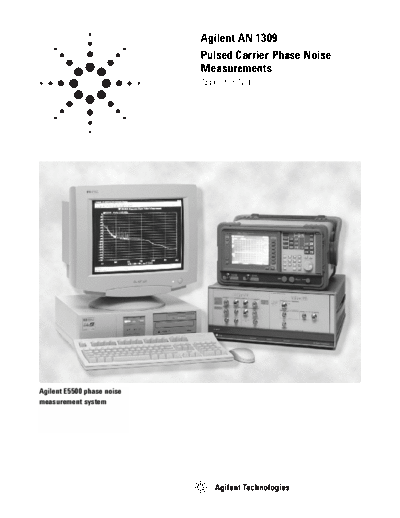
Agilent E5500 phase noise
measurement system
         Table of Contents


     3   Chapter 1
         Introduction

     4   Chapter 2
         Fundamentals of Pulsed Carriers
         Time Domain Representation
         Frequency Domain Representation

    10   Chapter 3
         How Pulse Modulation Affects the
         SSB Phase Noise of a CW Carrier
         Convolution of CW Carrier Spectra
           and Pulsed Waveform Spectra
         Noise Aliasing With Pulse Modulation
         Mathematical Equation for a Pulsed RF Carrier
         Decrease in Carrier Power
         Decrease in Pulsed Carrier Spectral Power

    16   Chapter 4
         How Pulsing the Carrier Affects the
         Phase Detector Measurement Technique
         System Noise Floor
         Measurement Offset Range
         Mixer dc Offset
         Recommended Hardware Configurations
         LO AM Noise Suppression
         Phase Transients
         PRF Feedthrough
         Minimum Duty Cycle
         Summary


2
Chapter 1


Introduction                                            absolute noise of individual oscillators but to know
Advances in RF and microwave communication              the residual or additive noise of signal processing
technology have extended system performance to          devices like power amplifiers and pulse modulators.
levels previously unattainable. Design emphasis on      Because the final signal in most radar systems is
sensitivity and selectivity have resulted in dramatic   pulsed, making absolute phase noise measurements
improvements in those areas. However, as factors        on the pulsed carrier is essential to determining
previously limiting system performance have been        the overall performance of the system.
overcome, new limitations arise and certain para-
meters take on increased importance. One of these       This application note discusses basic fundamentals
parameters is the phase noise of signal sources         for making pulsed carrier phase noise measurements.
used in pulsed RF and microwave systems.
                                                        The assumption is made that the reader is familiar
In pulsed radar systems, for example, the phase         with the basic concepts of phase noise and CW
noise of the receiver local oscillator sets the mini-   phase noise measurement techniques.
mum signal level that must be returned from a
target in order to be detectable. In this case, phase   Chapter 2 reviews the fundamentals of pulsed
noise affects the selectivity of the radar receiver     carriers in the frequency and time domains. The
which in turn determines the effective range of the     majority of terms used in succeeding chapters are
overall system.                                         defined throughout Chapter 2. Chapter 3 discusses
                                                        how the single sideband phase noise of a CW carrier
Since the overall dynamic range of the radar sys-       is affected by the pulse modulation process. Chap-
tem is influenced by the noise of the transmitted       ter 4 discusses the effects a pulsed RF carrier has
signal, it is not only important to know the            on the performance of a phase detector based
                                                        measurement.


                                                                                                           3
Chapter 2


Fundamentals of Pulsed Carriers                      the amplitudes of the higher order harmonics are
The formation of a square wave from a fundamen-      relatively small, so reasonably shaped rectangular
tal sine wave and its odd harmonics is a good way    waves can be produced with a limited number of
to begin a discussion of pulsed carriers and their   harmonics. By changing the relative amplitudes
representation in the time and frequency domains.    and phases of the harmonics, both odd and even,
                                                     an infinite number of waveshapes can be plotted.
You might recall having plotted a sine wave and
its odd harmonics on a sheet of graph paper, then    To create a train of pulses (i.e., a waveform whose
adding up all the instantaneous values. If there     amplitude alternates between zero and one) with a
were enough harmonics plotted at their correct       series of sine waves, a dc component must be added.
amplitudes and phases, the resultant waveform        Its value equals the amplitude of the negative loops
would begin to approach a square wave. The funda-    of the rectangular wave with the sign reversed.
mental frequency determined the square wave
rate, and the amplitudes of the harmonics varied     Consider a perfect rectangular pulse train as shown
inversely to their number.                           in Figure 1a, perfect in the sense that the rise time
                                                     is zero and there is no overshoot or other aberra-
A rectangular wave is merely an extension of this    tions. This pulse is shown in the time domain and
principle. In fact, to produce a rectangular wave,   if we wish to examine it in the frequency domain it
the phases must be such that all the harmonics       must be broken down into its individual frequency
go through a positive or negative maximum at the     components. Figure 1b superimposes the funda-
same time as the fundamental. Theoretically, to      mental and its second harmonic plus a constant
produce a perfectly rectangular wave, an infinite    voltage to show how the pulse begins to take shape
number of harmonics would be required. Actually,     as more harmonics are plotted.


                                 T


    E
                                                         A


                                     TIME

Figure 1a. Periodic rectangular pulse train


4
A spectrum analyzer would in effect "unplot" these                      to the PRF. The envelope of this plot follows a
waveforms and present the fundamental and each                          sinX/X function with the spectral line frequencies
harmonic in the frequency domain.                                       a fLINE = n X 1/T, for n = 1,2,3.... Note that the
                                                                        nulls occur at integer multiples of the reciprocal
A frequency domain plot of this waveform would                          of the pulse width.
be as shown in Figure 2. This is an amplitude versus
frequency plot of the individual waves which would                      Before proceeding on to a discussion of modulating
have to be added together to produce the waveform.                      a CW RF carrier with a pulsed waveform, let's
Since all the waves are integer multiples of the fun-                   define the terms used to represent the character-
damental (PRF), the spacing between lines is equal                      istics of a pulsed waveform.


                                                                                                T
                   Fundamental                    Sum of Fundamental,
   Average                                        2nd Harmonic and
   Value of                                       Average Value
   Wave
                           2nd Harmonic

                                                                         E
                                                                                                                          Epk
                                                                                EAVG

                                                                                                    TIME


Figure 1b. Addition of a fundamental cosine wave and its                Figure 3. Basic characteristics of a pulsed waveform
harmonics to form rectangular pulses


                                 Spectral Lines

                                                         y = sin x
                                                               x
      Amplitude


                          1
                          T
                  DC
                                          FREQUENCY, f


Figure 2. Spectrum of a perfectly rectangular pulse. Amplitudes and phases of
an infinite number of harmonics are plotted resulting in a smooth envelope as
shown.
                                                                                                                                5
Referring to Figure 3:                             With this background we can now apply the pulsed
                                                   waveform as amplitude modulation to a continuous
                                                   wave RF carrier. A pulsed carrier is typically a
                                                   continuous wave carrier whose amplitude is modu-
                                                   lated by a rectangular pulse train having a relative
                                                   amplitude of one during each pulse and zero dur-
                                                   ing the period between pulses. Pulsed carriers can
                                                   also be generated by pulsing a frequency generat-
                                                   ing device, such as an oscillator, on and off. One
                                                   of the fundamental differences between these two
                                                   methods is that an amplitude modulated CW carrier
                                                   is phase continuous from pulse to pulse, whereas
                                                   the phase of a frequency generating device, which
                                                   is pulsed on and off, is random. Most measurement
                                                   systems, using the phase detector technique, can
                                                   only measure the phase noise of phase continuous
                                                   signals. The phase detector technique requires that
                                                   the two input signals be at quadrature (i.e., 90
                                                   degrees out of phase). If quadrature is lost, the sys-
                                                   tem will terminate the measurement. Quadrature
                                                   cannot be maintained if the phase from pulse to
                                                   pulse is random.


          pulse is on during one complete cycle.


6
From single tone AM modulation theory we know                  The spectral line frequencies can be expressed as:
that sidebands will be produced above and below
the carrier frequency. The concept is the same for               FL = FC
◦ Jabse Service Manual Search 2026 ◦ Jabse Pravopis ◦ onTap.bg ◦ Other service manual resources online : Fixya ◦ eServiceinfo