Service Manuals, User Guides, Schematic Diagrams or docs for : HP Publikacje HP-Bench-Briefs-1974-07-08
<< Back | HomeMost service manuals and schematics are PDF files, so You will need Adobre Acrobat Reader to view : Acrobat Download Some of the files are DjVu format. Readers and resources available here : DjVu Resources
For the compressed files, most common are zip and rar. Please, extract files with Your favorite compression software ( WinZip, WinRAR ... ) before viewing. If a document has multiple parts, You should download all, before extracting.
Good luck. Repair on Your own risk. Make sure You know what You are doing.
Image preview - the first page of the document
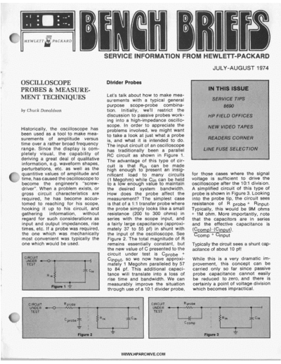
>> Download HP-Bench-Briefs-1974-07-08 documenatation <<
Text preview - extract from the document
                                 SI              i l l


                                        SERVICE INFORMATION FROM HEWLETT-PACKARD
                                                                                          JULY-AUGUST 1974

OSCILLOSCOPE                            Divider Probes
PROBES & MEASURE-
                                        Let's talk about how to make mea-
MENT TECHNIQUES                         surements with a typical general
                                        purpose scope-probe combina-
by Chuck Donaldson                      tion. Initially, we'll restrict the
                                        discussion to passive probes work-
                                        ing into a high-impedance oscillo-
                                        scope. In order to appreciate the
Historically, the oscilloscope has      problems involved, we might want
been used as a tool to make mea-        to take a look at just what a probe
surements of amplitude versus           is, and what it is intended to do.
time over a rather broad frequency      The input circuit of an oscilloscope
range. Since the display is com-        has traditionally been a parallel
pletely visual, the capability of       RC circuit as shown in Figure 1.
deriving a great deal of qualitative    The advantage of this type of cir-
 information, e.g. waveform shapes,     cuit is that Rin can be .made
 perturbations, etc. as well as the     high enough to present an insig-
 quantitive values .of amplitude and    nificant load to many circuits          for those cases where the signal
 time, has caused the oscilloscopeto     (1 Megohm) while Cin can be he!d       voltage is sufficient to drive the
 become the engineer's "screw-          to a low enough value to maintain       oscilloscope after the 1O:l division.
 driver". When a problem exists, or     the desired system bandwidth.           A simplified circuit of this type of
 gross circuit characteristics are      How does the probe affect the           probe is shown in Figure 3.Looking
 required, he has become accus-         measurement? The simplest case          into the probe tip, the circuit sees
 tomed to reaching for his scope,       is that of a 1:l transfer probe where   resistance Of R probe + Rinput.
 hooking it up to his circuit, and      the probe simply looks like a small     Typically, this would be 9M ohms
 gathering information, without          resistance (200 to 300 ohms) in        + 1M ohm. More importantly, note
 regard for such considerations as      series with the scope input, and        that the capacitors are in series
 input and output impedances, rise      a fairly large capacitance (approxi-    and the effective capacitance is
 times, etc. If a probe was required,    mately 37 to 55 pf) in shunt with       (Ccomd (CinDut).
 the one which was mechanically         the input of the oscilloscope. See        Ccomp + Cinput
 most convenient was typically the       Figure 2. The total magnitude of R
 one which would be used.                remains essentially constant, but      Typically the circuit sees a shunt cap-
                                        the new value of C presented to the     acitance of about 10 pf!
                                         circuit under test is Cprobe +
                                         Cinput, so we now have approxi-        While this is a very dramatic im-
                                         mately 1 Megohm paralleled by 57       provement, this concept can be
                                         to 84 pf. This additional capaci-      carried only so far since passive
                                         tance will translate into a loss of    probe capacitance cannot easily
                                         rise time and bandwidth. We can        be reduced to zero, and there is
                                         measurably improve the situation       certainly a point of voltage division
                                         through use of a 1O:l divider probe,   which becomes impractical.
                               TOOLS AND TECHNIQUES


Active Probes                            Measurement Accuracy                             Readinn the CRT, YOU answer
                                                                                                -
                                                                                          10 ns. Right? Maybe yes, and
                                                                                                                             0
Active probing devices are the           Let's now consider measurement                   maybe no.
highest resistanceAowest capa-           accuracy. Suppose you feed the                   Although 10 ns is the reading of the
citance probes available today.          output of a pulse generator                      scope display, this value may not
An active probe with a 1 O : l divider   through a probe to an oscilloscope.              be the true rise time of the pulse.
can provide an input resistance of       You adjust the scope time base                   Ignoring scope inaccuracies, what
1 Megohm shunted by about 1 pf           for a fast sweep. (This is the typical           other reason is there for suspecting
of capacitance. These active probes      setup for measurement of rise                    that the measurement is not the
are typically used with oscillo-         time). The result is the familiar                real rise time?
scopes that have vertical amplifiers     rise-time waveform shown in                      Basically, when the pulse passes
with a 50 ohm input impedance.           Figure 4. If the time base is set for            through the probe, the scope ampli-
                                         a sweep of 5 nanoseconds per divi-               fier, and even the scope CRT, it
                                         sion, what is the rise time of the               suffers rise time deterioration.
                                         generator's output pulse (ignoring               Thus, the displayed waveform
                                         any inherent scope inaccuracies)?                doesn't represent the true, original
                                                                                          signal.
                                         Figure 4. Pulse rise time is measured between    Although this is an unfortunate
                                         the 10% and 90% points on the leading edge       circumstance, it has one saving
                                         of oscilloscope trace. in this case, rise time   grace: it can be predicted. So if
                                         is 10 ns.                                        you erroneously said that the rise
                                                                                          time in the example was 10 ns, it
                                                                                          should be both interesting and
Active probes aren't usually                                                              informative to learn how to deter-
thought of as general purpose                                                             mine what the error might be.
probes, and because they are more                                                         True rise time can be determined
expensive, more care needs to be                                                          by the use of the tongue-twisting'
taken in their use. Suffice is to say                                                     formula known as the "square
that when working at very high fre-                                                       root of the sum of the squares."
quencies (above 300 MHz or so),                                                           In mathematical terms:
there are different probes and tech-
                                                                                           TRG= \ J T R D ~ T R S ~
                                                                                                             -
niques available to obtain more
accurate results (e.g. sampling                                                            where TRG = true signal generator
osci Iloscopes).                                           5 nsldiv                        rise time


                                                      WWW. HPARCHiVE.COM
                                                                      TOOLS AND TECHNIQUES           -m
                                                                                                     1
TRD = displayed risetime
  ~
                                                     whose true risetimes are 10 ns. Ten      True Signal Risetime = 3.2
TRS = osciIloscope/probe system                      divided by 3.5 is 2.9. Using Figure 5,            3.5 ns
risetime.                                            the error is 6%.
                                                                                              True Signal Risetime = (3.5)(3.2)
For a 50 MHz oscilloscope/probe                      Let's look at the problem another                              = 11.2 ns.
combination, the risetime is 7 ns.                   way. Suppose we want our mea-
Putting this into the formula, we                    surements to be within 5%. What          Rearranging our formula,
get:                                                 is the fastest risetime we could
                                                                                              TRD = \ ~ T R G + TRS
                                                     view on the CRT without going
T R G = I / ~ = 7.1ns=       ~                       over 5% in error? Going to the 5%            = 511.2   + 3.5   *   = 11.7 ns
The actual risetime of the pulse                     point on Figure 5, the ratio is 3.2.
generator is 7.1 ns, not 10 ns. The                  For our 3.5 ns system (TRS = 3.5).                             Continued on Page 8
measurement was in error by about
41%.

                                                                                              graph of resistance versus fre-
                                                       The input capacitance of a scope       quency, with capacitance as the
                                                       is held to a value such that the       variable parameter, we can.
                                                       desired system bandwidth can           easily determine the source re-


                                                               he measurement. How im-        Figure A.


  1     1.5   2   2.5 3   4   5        8   7

Figure 5. Measurement Error       V
                                  .I       Signal/
System Rlse Time Ratio

It is important, therefore, to keep in
mind that the displayed risetime is
greater than the actual risetime.
The amount of error can be deter-
mined from the graph in Figure 5.
Here, percent of error is plotted
against the ratio of test system rise
time over true signal risetime. As
an example, suppose you are using
a 100 MHz oscilloscope/probe
combination that has a rise time of
3.5 ns. You are examining signals


                                                            WWW.HPARCHIVE.COM
 vi.
   *I
                       i .-.-
◦ Jabse Service Manual Search 2026 ◦ Jabse Pravopis ◦ onTap.bg ◦ Other service manual resources online : Fixya ◦ eServiceinfo