Service Manuals, User Guides, Schematic Diagrams or docs for : HP Publikacje HP-Bench-Briefs-1974-09-10
<< Back | HomeMost service manuals and schematics are PDF files, so You will need Adobre Acrobat Reader to view : Acrobat Download Some of the files are DjVu format. Readers and resources available here : DjVu Resources
For the compressed files, most common are zip and rar. Please, extract files with Your favorite compression software ( WinZip, WinRAR ... ) before viewing. If a document has multiple parts, You should download all, before extracting.
Good luck. Repair on Your own risk. Make sure You know what You are doing.
Image preview - the first page of the document
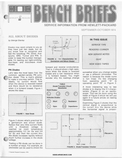
>> Download HP-Bench-Briefs-1974-09-10 documenatation <<
Text preview - extract from the document
P
L l
C
SERVICE INFORMATION FROM HEWLETT-PACKARD
SEPTEMBER-OCTOBER 1974
#
! ALL ABOUT DIODES
`I by George Stanley
Diodes may seem simple to you as
they have just two leads, but do
you know how to recognize and
test the following: PN, Zener, Ava-
lanche, SRD, Tunnel and PIN. In
Order to keep the number manage-
able I'm leaving out light-emitting,
four-layer, and microwave mixer
diodes.
forward and reverse conductance.
PN Diodes That is, it should show a high resis-
tance when the diode is reversed somewhat when you change scales
Let's take the most basic first: the biased and a low resistance when
common, garden-variety PN junc- or use a different ohmmeter. The
it is forward biased. You might
.
..-t ion diode. This is man's attempt
to make a one-way switch. That is,
ideally, no current would flow
wonder why the readings change
reason is because the diode curve
is non linear. It's like changing
from operating point "A' to
when the device is reversed biased operating point "B" in Figure 2.
and there would be no resistance A more interesting way to test
when it is forward biased. Figure 1 diodes is to display the V-l charac-
shows the ideal. teristic (Figure 2) on an oscillo-
scope. This can be done using the
tester of Figure 3 which we will use
again in a future article on testing
transistors.
Examining Figure 3 shows that the
vertical signal is proportional to
the current thru the device while
the horizontal signal is propor-
Figure 2 shows what's practical for
a germanium and silicon diode.
Notice that very little current flows
until a threshold voltage is
reached (at room temperature
approximately 0.2 for Ge and 0.6
for Si) and then the current thru
the diode increases rapidly without
much further increase in the diode
voltage.
Testing a PN diode can be done in
51number of ways. For example, an
ohmmeter can be used to check the
\
@ Hewlett-Packard Company 1974
WWW. H PARCHIVE.COM
SERVICE TIP
I
tional to the voltage across the as the temperature is increased).
device. (The two 70K resistors are This difference comes about from
only to protect delicate diodes or the different way breakdownoccurs.
transistors if shorts develop in the Simply put, in the Zener diode (up
scope cables.) to about 5V) electrons are freed by
Using this tester and the associated the applied field being strong
table of waveforms you can rapidly enough to suddenly rip electrons
determine if a diode is open or out of the lattice structure and put
shorted. It also tells if there is asso- them into the conduction band.
ciated resistance or capacitance In the Avalanche diode (above
from neighboring components about 7V) the energy gap is wider
such as on a PC board. This is a and before Zener action occurs,
valuable tester which really comes free electrons are accelerated to
into its own when you want to a velocity high enough to knock
rapidly test the emitter-base and out lattice bound electrons during Step Recovery Diode (SRD)
basecollector diodes on a many- collisions. In the 5-7 volt region
transistor PC board. breakdown diodes often exhibit
a nearly flat T.C. because both The Step Recovery Diode is a
r . ' .
processes are occurring and com- special PN junction diode. It has
pensate each other to a certain ex- heavy doping near the junction
tent. Figure 5 shows how a PN which gives it a long charge stor-
junction diode with its negative age, but when carrier recombi-
T.C. can be used to compensate the nation ends (electrons falling into
positive T.C. of an avalanche holes) it ends abruptly and the
diode. device switches off very rapidly.
FIGURE 4. Diode V-r and Heat Figure 6 shows the current thru
Applications of the PN diode are
many. Leading the list are recti-
the device as a function of time.
Since this diode aenerates a very
sharp "on-to-off" transition (Point
a
fiers, switches and temperature A, Figure 6) it is often used as a
compensators. The garden-variety harmonic generator. Testing can
PN diode has a negative T.C., or
usually be done with the diode
temperature coefficient, and this checker or with an ohmmeter
property is often used to counter-
(watch you don't use the R x l scales
act the positive T.C. of the Ava-
as it may put out a very high short
lanche diode. Figure 4 shows the
circuit current). Look for opens or
reason for the -T.C. When heat is
shorts. If you want to experiment
applied, the diode tries to turn on a little, you can display the wave-
harder and its resistance falls. The form of Figure 6. You will need a
current is limited by the 10K resis- high frequency scope (50 MHz or
The diode tester (Figure 3) can be
tor so the diode voltage must fall. higher) and at least a 500 kHz
Try it yourself. All you need is a used to check breakdown diodes
if they break down below about oscillator driving source. The
battery (borrow the one out of arrangement of Figure 7 shows the
your wife's radio), a resistor, 9 volts (6.3 volts of the transformer
xl.4 14). detailed connections.
soldering iron for heat, and your
multimeter to track the voltage as
you heat the diode.
Zener and Avalanche Diodes
Both Zener and Avalanche diodes
are breakdown diodes (see Figure 2)
but the Zener diode has a negative
T.C. (the breakdown voltage falls
as the temperature is raised) while
the Avalanche diode has a positive
T.C. (the breakdown voltage rises
WWW.HPARCHIVE.COM
a Tunnel Diodes
George Stanley, a member of in the area of technical educa-
I.E.E.E., received his B.S.E.E. tion, and is the author of Tran-
Tunnel diodes are not as compli- degree from Stanford University. sistor Basics: A Short Course. He
cated as you have been told. Figure He is very interested and active also created a fifteen-part video
8 shows their V-l characteristics. tape series entitled "Practical
Transistors".
Prior to becoming involved in
technical education, George was
a microwave development engi-
neer and holds a patent in the
area of control circuitry. Present-
ly, he is Product Training Mana-
ger for our Electronics Products
Group in Palo Alto, California.
He lives in Los Altos, California
with his wife and their three
children.
wave transmission line and a DC sink in the middle of a microwave
Because of very heavy doping, the transmission line. However, some-
gap between electrons on the N bias is applied to the diode. This
bias injects a large number of holes times after shorting the diode will
material side and holes on the P open internally due to the heat
material side of the PN junction is and electrons into the intrinsic
region. This large amount of stored produced when it first shorted. You
much narrower than in the plain can expect to find both situations.
charge means the diode continues
PN junction. The result is electrons Not only are PIN diodes somewhat
to partially conduct even during
tunneling after holes and vice
the reverse bias part of the RF delicate but you have to be careful
versa even without bias. When for- soldering them into the circuit as
ward bias is applied, conduction cycle. This is the key to its applica-
tion. Note it does not act like a you don't want to set up a mis-
starts immediately as conduction match on the transmission line.
band electrons (N material) find diode but rather as variable resis-
themselves next to valance band tor. The amount of resistance
(attenuation) is a function of the There are at least as many diodes
holes (P material) and the tunnel I've left off as I've covered, but
occurs with vengence. This con- d-c forward bias, i.e. the more bias,
the more stored charge and the hopefully this short article will give
tinues during region 1 on Figure 7. you more insight into these fas-
Current peaks at point 2 and then greater the attenuation.
cinating devices. In a future article
decreases because the gap between Failures are usually by shorting as I would like to cover rapid transistor
N side electrons and P side holes it's difficult to provide a large heat testing.
increases and becomes too wide
for tunneling. Current falls off
very rapidly until it intersects the
"normal" diode curve at 3.
ATTENTION 260A and the Q Voltmeter tube HP part
Many tunnel diodes can be tested number 00260-80005. We are
using the diode checker of Figure Q METER OWNERS!!! making every effort to continue
3, but put the switch in the "In to supply these spare parts until
Circuit" position to obtain the 1978, but recent unavailability of
proper cu rrentholtage relationship. The Boonton 260A Q Meter was vendor parts has caused some
introduced in 1952 and obsoleted eight months delay in filling some
The PIN Diode in April 1973. Two critical re- orders for these parts. We suggest
placement parts for this model that users review their require-
depend upon the ability of out- ments for their 260A Q Meters
The PIN diode consists of P mate- side vendors to supply sub- and consider ordering spare parts
rial, Intrinsic material, and N now for anticipated future needs,
assembly parts, some of which
material. The intrinsic material is and also consider replacing these
are made with 40-year old tool-
quite wide and is the key to its units with the modern HP 4342A
ing. These are the thermocouple
operation which is as a microwave and 4343A Q meters.
attenuator. In a typical application HP part number 00260-60079,
the PIN is placed across micro-
zation has been assigned the addi- 0
n t ional responsibiIit y -for providing
this service. This video tape is de-
signed to give the CE a brief
introduction to the 5526A Laser
System, its theory of operation,
L hardware, and how to perform on-
1 site diagnosis and repair. This
tape, together with data sheets,
application notes, and service
I manuals, forms the basic package
L
of introductory training material
for the CE. For additional informa-
tion, it is recommended that you
Here's your chance to share your Ideas and views with other Bench Briefs reclplents. In view the following tape (90281-).
Reader`s Comer, we wlll prlnt letters to the Editor, troubleshooting tips, modlficatlon In-
formation, and new tools and products that have made your Job easier. In short, Reader`s
Corner will feature anythlng from readers that I of general Interest to electronic service
s 5501A ON-SITE SERVICE ..
personnel. MADE EASIER
If there I something you have to share with other Bench Briefs readers, let us hear from you.
s
(90281-) 30 minutes. This vid-
Dear Sirs: Several clues were intentionally misleading eo tape is designed to give the CE
or redundant. This one caused a little more a brief introduction to the 5501A
confusion than I intended, however.
Your excellent publication "Bench Briefs" is Laser System, its theory of opera-
being received here regularly with consider- Editor
able interest, and is found to be very informa- tion, applications, hardware, and
tive and constructive. My particular work Dear Sir: how to perform on-site diagnosis
activity involves supervising an APO calibra- and repair. This tape, along with
tion and repair depot for radio communica- The probe article in July-August issue
tions, T V transmission and broadcasting "pulled it all together". I'm horrified to
data sheets, application notes, and
testing instruments, and so "Bench Briefs" think that some people use probes as service manuals, forms the basic
provides a valuable source of information in "tow cables"! On page 2, right column, it package of introductory training
this area for our HP instruments. might be more accurate to say "square root
of the differences of the squares". material for the CE. For additional
As requested, I have completed the opinion information, it is recommended
page in the March/April 1974 issue, and it is I knew capacitance is a problem, but that you view the program "5526A
Figure A, page 3, is still a bit of a surprise.
enclosed herewith. By way of explanation of
this opinion, I feel that "Bench Briefs" On-Site Service . . . Made Easier
should retain its present character of service N. Bodley (90280-)."
advice and not enter too much into detailed 300 West 108th
explanations on devices, circuits or instru- New York City, N.Y. 10025
ments which I consider to be adequately 1220N1221A SERVICE HINTS
covered in other HP publications such as the
Journal, Application Notes, System Descrip-
tion Notes, Equipment Manuals. etc.. and I hope the article did not teach a new way to (90252-) 19 minutes. Using only
which are always readily available here in abuse a scope probe. four circuit modules in addition to
Australia. Editor the CRT, these low cost oscillo-
scopes are designed for easy ser-
Your recent quiz in the January/February vicing. Removing a circuit assem-
1974 issue has caused some consternation in
the office here, in particular with reference bly from the chassis makes it
to clue (j). When taken in a strictly literal easier to replace faulty components
sense, it can be argued that the American NEW VIDEO TAPES by providing access to both sides
has not been excluded from 4th place. He
could in fact have a mother-in-law who is of a circuit board. This video tape
bigger than he is (heaven help him), and Here are some new video tapes demonstrates the removal and re-
actually be the driver who finished in 4th
place, thus making clue (j) redundant. In fact, that will be of interest to service placement of the CRT, all circuit
the problem is unresolvable if this is so. personnel. assemblies, and the use of the ex-
tender boards and cables.
Considerable discussion ensued as to
whether it was intended that this clue be
deliberately misleading or whether it was
one of those rare cases where HP has made
5526A ON-SITE SERVICE .. Contents of this tape is also cov-
ered in Service Note 1220A-3/
a small error! MADE EASIER 1221A-1. See Service Note Index.
Yours faithfully,
(90280-) 28 minutes. With the
Brian Hey change in Laser System warranty
Senior Telecommunications Technical policy to include 90-day on-site To obtain more details or to place
Officer service for non-OEM customers, an order, please contact your
REGI ONAL OPERATIONS
Australian Post Office the Customer Engineering organi- local HP office.
WWW. H PARCHiVE.COM
NEW SERVICE NOTES
I'
NEED ANY SERVICE 333Al334A DISTORTION ANALYZER
333/334A-7. 333A serial numbers 980-01886 and
1220Nl22lA OSCILLOSCOPES
1220A-2 Serial numbers 1461A01300 and below.
Low frequency triggering.
NOTES? above. 334A serial numbers 993-02841 and above.
Modification kit to eliminate RFI induced 1220A-3/1221A-l All serials. Removal and
replacement of assemblies.
through the floating sensitivity switch.
1220A-4/1221A-2 All serials. Normal trigger
400D/H/L VACUUM TUBE VOLTMETERS mode.
Here's the latest listing of Service 400D/H/L-14. 4 w D serial numbers 1247A59465
1220A-5 Serial numbers 1416A01815 and above.
New safety plate.
a Notes available for Hewlett-Packard
products. Service Notes contain infor-
mation that will help you get the most
out of your purchases.
and below. 400H serial numbers 1248A38061 and
below. 4OOL all serials. Flattening frequency
response.
403AlB AC TRANSISTOR VOLTMETER
403A-3tV4038-4A All serials. Meter circuit
diode replacement.
1310A/1311A COMPUTER GRAPHIC DISPLAY
1310A-7A Serial prefix 1301A and below; super-
cedes 1310A-7. Improved HV power supply.
1310A-8A Serial prefix 1406A and below; super-
cedes 131OA-8. Modification to reduce coupling
between the Z-axis input and the X/Y inputs.
4038-6 Serial numbers 523-05300 and below; 1311A-7A Serial prefix 1238A and below;
sumrcedes 40384. Modification to reDlace supercedes 1311A-7. Improved HV power
Many times design changes or other germanium transistors with silicon transistors supply.
and associated resistances. 1311A-8A Serial prefix 1405A and below; super-
improvements are made in products 4038-7 Serial numbers 0986A16446 and below. cedes 1311A-8. Modification to reduce coupling
currently being manufactured. HP of- Possible safety hazard: analog low may be between the Z-axis input and the X/Y inputs.
shorted to case ground. 1330A X-Y DISPLAY
ten recommends including these 419A DC NULL VOLTMETER 1330A-3 Serial prefix 1340A and below. Pre-
changes in products previously sold; 419A-7 All serials. Elimination of potential ferred replacement for HV rectifier diodes.
shock hazard. 1330A-4 Serial prefix 1340A and below. Pre-
this is done by writing a Service Note ferred resistor replacements.
461Al462A GENERAL PURPOSE/
for the product. PULSE AMPLIFIERS 133OA-5 All serials. Improved power transistor
connection method.
461/462A-3. 461A serial numbers 0946A04790 and
below. 462A serial numbers 0647A01625 and 1331A X-Y DISPLAY, STORAGE
below. Improve gain bandwidth product. 1331A/C-7. 1331A serial prefix 1319A and below,
Service Notes for your instruments 467A POWER AMPLIFIER SUPPLY 1331C prefix 1318A and below. Preferred re-
placement for HV rectifier diodes.
can be obtained by using the Service 467A-2 Serial numbers 0994A03170 and below.
Crossover distortion. 1331A/C-8. 1331A serial prefix 1319A and below.
Note Order Form. Remove the order 651A TEST OSCILLATOR 1331C prefix 1318A and below. Preferred resis-
form and mail it to the HP distribution 651A-78 All serials; supercedes 651A-7A. tor replacements.
Conversion of output monitor to DBM/GOO ohms. 1331NC-9 All serials. Improved power tran-
center nearest you. sistor connection method.
6518 TEST OSCILLATOR
6518-U-1000 Serial numbers below 1201UOO925. 17OOB OSCILLOSCOPES
Power transistor replacement. 17008-1 Serial prefix 1225A and below.
Improved low frequency triggering.
GENERAL 654A TEST OSCILLATOR 1707B OSCILLOKOPES
654A-1 Serial numbers 0951A01520 and below.
M458 Cleaning and lubricating rotary switches; Reduce high frequency distortion. 17078-4 All serials. Modification to change syn-
supercedes M45A. chronized chop mode to a free-running chop
738BR VOLTMETER CALIBRATOR mode.
7388R-3 All serials. Correct part number for 2930A LOW LEVEL MULTIPLEXOR
214A PULSE GENERATOR C5 and C10. 12722A-2 All serials; supercedes P12722A-1.
214A-8 All serials. Product safety compliance. 740B DC STANDARD/DIFFERENTIAL Update of service kit.
VOLTMETER 3310AlB FUNCTION GENERATOR
302A WAVE ANALYZER 7408-4A Serial numbers 722-00790 and below;
supercedes 7408-4. K1 low line voltage 3310NB-5. 3310A serial numbers 1151A05900
302A-5 All serials. Crystal set replacement. modification. and below. 33108 serial numbers 1201A00950
and below. A more reliable AlC14.
331Al332A 970A PROBE ,MULTIMETER 3330A/B AUTOMATIC SYNTHESIZER
970A-1 All serials. Service guide for 970A probe. 333OA/B-4 All serials. Option 002 crystal
DISTORTION ANALYZER
1208A DISPLAY oscillator.
331/332A-8. 331A serial numbers 982-04451 and Hll-1208A-7 Serial prefix 133OA and below. 34oaA RMS VOLTMETER
above. 332A serial numbers 98501991 and Preferred replacement for HV rectifier diodes. 3400A-U-lo00 Serial numbers 1232U01515 and
above. Modification, kit to eliminate RFI induced H11-1208A-8 All serials. Improved power tran- below. Replacement of power regulator
through the floating sensitivity switch. sistor connection method. transistor.
WWW. H PARCHIVE.COM
34506 MULTI-FUNCTIONMETER 5310A BATTERY PACK 866OA-23 Serial Drefix 1404A and below.
345051 AC zeroing problems. 5310A-7 All serials. Battery replacements. Improved mainframe ower relays.
34508-2 Intermittent transfer. 532W5327NBlC UNIVERSAL COUNTERS 86608-20 Serial prelx 1402A and below.
3460A/B3461A/3462A 5326/5327A-8,5326/53278-8, 5326/5327C-8 Power supply fuse change.
All serials, display tube driver warning. 86608-21 Serial prefix 1404A and below.
DIGITAL VOLTMETER Improved mainframe power relays.
5326/5327A-9,5326/53278-9,5326/5327C-9
346OA/B-1, 3460A-3, 3462A-4 All serials. Repair All serials. Update on +175V protection circuit 86908 SWEEP OSCILLATOR
of the ohms oven assembly. for +175V power supply. 86908-9 Serial prefix 1202A and below.
340OA/B DIGITAL VOLTMETER Recommended replacement for A8C4 and A8C5.
3480NB-4 All serials. Improve reliability.
535414 AUTOMATIC
9662A X-Y PLOTTER
348OA-5 Serial numbers 1128A00845 and below. FREOUENCY CONVERTER 9862A-6 All serials. Mechanical parts list
Oscillation on the -2OV supply. 5354A-2 Serial numbers 1404A00125 and below. correction.
34808-5 Serial numbers 1127A01550 and below. Capacitor change to stop false locking when 7203A-2/7210A-4/9862A-7 AI I ,serials. Modify-
Oscillation on the -2OV supply. measuring -1.5 GHz to 2.0 GHz. ing pen lift assemblies and springs.
3480A/B-6 All serials. Recommended replace- 5354A-3 Serial numbers 1404A00125 and below. 7200A-4/7201A-1/7?02A-4/7203A-3/7201 A-5/
ment for nixie driver. Component changes to prevent erratic counts 9862A-8 All serials. Differences between pen
3482A DC RANGE UNIT when in the manual CW and manual or Auto- lift solenoids.
3482A-1A Serial numbers 1133A00700 and I
PRF modes of operation. 9862A-9 All serials. Interface cable conversion.
below; supercedes 3482A-1. Compatibility 9862A-10 All serials. Electrical alignment pro-
problem with 3480C/D. 7000/7001A X-Y RECORDERS cedures to be performed after changing the
3482A-2 Serial numbers 11334400775 and below. 7OOOA-7, 7001A-2 Early serials. Fan motor servo pre-amp or mechanical assembly.
Intermittent logic problem on 100mV, l V , or deletion. 9862A-11 All serials. Test program for electrical
l 0 0 V range. 70048 X-Y RECORDER alignment of the 9862A with the 9830A
3482A-3 Serial numbers 1133A00711 and 70048-7 Serial numbers 1240A04224 to calculator.
below. Intermittent false triggering. 1340A04557 (approx.). Rerouting of fuse 9869A I/O EXPANDER
3484A MULTI-FUNCTIONUNIT board wiring. 9869A-4 All serials. Read head remedies.
FOR 348OA/B 7090A X-Y RECORDER 11531A CALIBRATOR
3484A-2 Serial numbers 1124A01494 and below. 703OA-3 Early serials. Fan motor deletion 11531A-1 Serial prefix 1140A and below.
Intermittent false triggering. recommended. Recommended replacement for AlC3.
3485A SCANNING UNIT 7 W X-Y RECORDER 12750 S/H AMPLIFIER
3485A-1A All serials' supercedes 3485A-1. 7046A-1 All serials. Pen overtravel, lift, and 127508-1 Serial prefix 1202A through 1317A.
Incorrect timing of remote "Program Acknowl- separation adjustments. C-21 change if Q18 replaced.
edge" line. Note: This service note applies to 7200/7201/7202/720~GRAPHIC PLOlTER 2-M DIGITAL TEST SUBSYSTEM
those instruments that have the inductor 7200/7202A-l All serials. Mechanical parts 28035A-1 All serials. Recommended spare parts
coupled remote essembly. list correction. for three levels of repair.
349OA MULTIMETER 7200/7202A-2 All serials. Mechanical parts list
correction. 28036A WAVEFORM
349OA-1 Serial numbers 1211A00806 to 7200/7202A-3 All serials. 115V line fuses.
1211A02255 (a prox.). Correct part number for PROCESSOR SUBSYSTEM
ASCII (option g30) optical isolators. 7200A-4/7201A-l/7202A-4/7203A-3/7201 A-5/ 28036A-1 All serials. Recommended spare parts
349OA-2 All serials. GPlB repair kit. 9862A-8 All serials. Differences between pen for three levels of repair.
lift solenoids.
0
349OA-3 All serials. Integrating capacitor part 7203A-W7210A-4/9862A-7 All serials. Modify-
28039A/B SYNTHESIZER SUBSYSTEM
number. ing pen lift assemblies and springs. 28039A-1 All serials. Recommended spare parts
3490A-4 Serial numbers 1211A02105 and below. for three levels of repair.
7203A-4 All serials. Electrical alignment pro-
Pulses on +5V dc supply. cedures to be performed after changing the 29400 SERIES,RACK CABINETS
349OA-5 Serial numbers 1211A01107 to servo pre-amp or mechanical assembly. 29400-1 Instrument slide failure.
1211A01535. Install A7C1 and A7C2 in the ohms 34703A DCVIDCA OHMMETER
converter. 721OA DIGITAL PLOTTER
349OA-6 Serial numbers 1211A02105 and below. 7210A-3 All serials. Mechanical parts list 34703A-2 All serials. Troubleshooting
Ratio assemblv IC socket shorts. correction. information.
349OA-7 All seiials. Service kit. 7203A-2/72lOA-4/9862A-7 All ,serials. Modify- 347216 BCD MODULE
ing pen lift assemblies and springs. 347218-1 All serials. Floating measurements
37028 IFIBB RECEIVER 7200A-4/7201A/7202A-4f7203A-3/7201 A-5/ using the BCD module.
37028-13 Serial numbers below 1249U00281. 9862A-8 All serials. Differences between pen
Field replacement of A23 assembly. 86341A/B. 86342A, AND 8835oA
lift solenoids. OSCILLATOR MODULES
3710A IF/BB GENERATOR 721OA-6 All serials. Electrical alignment pro- 86341NB-1. 86342A-2, 8635OA-3. 86341A all
371OA-1 All serials. Preferred replacement for cedures to be performed after changing the serials. 863418 serial prefix 1219A and below.
R4 its deviation calibration control servo pre-amp or mechanical assembly. 86342A prefix 1224A and below. 86350A prefix
potentiometer. 7260/7261A OPTICAL MARK READER 1239A and below. Modification to correct DC
3722A RANDOM NOISE GENERATOR 7260/7261A-7 All serials. Read error remedies. offset of sweep reference output.
3722A-5 Preferred replacements. 8403A MODULATOR 86602A RF SECTION
3736A DOWN CONVERTER PLUG-IN 86602A-5 Serial numbers 1305A00430 and
3736A-1 Serial numbers below 1307U00136. 8403A-7. Serial prefix 1251A and below. Improve-
ment in setability of 50 kHz rate. Improve AM below. Improved connector grounding.
Variations in YIG oscillator output power.
compatibility with 8730 PIN modulators.
3738A DOWN CONVERTER PLUG-IN
3738A-1 Serial numbers below 1320U00116. 85526 SPECTRUM ANALYZER, IF SECTION
Variations in YIG oscillator output power. 85528-8A Serial prefix 1311A and below;
3739A DOWN CONVERTER PLUG-IN supercedes 85528-8. Prevention o f , fuse blow-
3739A-1 Serial numbers below 1317U00116. ing in IF section due to false triggering of SCR.
Variations in YIG oscillator output power. 8555A SPECTRUM ANALYZER
3700A DATA GENERATOR 8555A-2 All serials. Precautions on replacing
376OA-1 Serial numbers below 1347U00156. input mixer assembly.
Field replacement of A42Q1 and A42Q4. 8620A SWEEP OSCILLATOR
3661A ERROR DETECTOR 8620A-28 Serial prefix 1218A and below; super-
3761A-1 Serial prefixes below 1349U. Pre- cedes 8620A-2A. A9/A10 switch/interconnect
ferred replacement for A42C1 and A43C1. board assembly replacement.
862OA SWEEP OSCILLATORS
4260A UNIVERSAL BRIDGE 8620A-3A All serials; supercedes 8620A-3.
426OA-4 All serials; supercedes 4260A-2. Illus- Installation of remote frequency programming
trated parts identification. capability (option 001).
5060A/SO6lA CESIUM BEAM 8640A/B SIGNAL GENERATORS
FREOUENCY STANDARD 86ONB-19. 8640A serial prefix 1413A and below.
5061A-5 All serials. Summary of important cir- 86408 prefix 1406A and below. Line switch
cuit modifications, recommended procedures modification.
and replacement parts. Some changes are also
applicable to model 5060A. 864ONB-20. 8640A serial prefix 1415A and below.
86408 prefix 1406A and below. Power supply
5306A MULTIMETER regulator improvements.
5306A-4 Serial numbers 1332A01761 and
below. High voltage insulator. 8 W B SYNTHESIZED SIGNAL GENERATOR
5306A-5 Serial prefix 1332A and below. Printer 8660A-22 Serial prefix 1404A and below.
output correction. Power supply fuse change.
WWW.HPARCHIVE.COM
NAME
ORDER FORM
COMPANY NAME
Please print your name and address clearly. ADDRESS
This will be used as a shipping label. e
CITY
0 Check here to receive a qualification form for
a free subscription to Bench Briefs. STATE ZIP
Please check below the numbers of any desired service notes:
E
Cut off this page and return to: 0 348OAfB-6 0 72OOf7202A-2
0 3482A-18 0 72OOf7202A-3
0 3482A-2 0 7200A-4f7201A-1
Hewlett-Packard 3482A-3 7202A-4f7203A-31
195 Page Mill Road 0 3484A-2 7201A-5f 9862A-8
Palo Alto, California 94306 0 7203A-2f72lOA-4f9862h-7
0 3485A-1A
0 3490A-1 0 7203A-4
For European customers (ONLY), 349OA-2 0 721OA-3
0 349OA-3 0 721OA-6
please send it to: 0 349OA-4 726Of7261A-7
0 8403A-7
Hewlett-Packard
0 3490A-5
Central Mailing Dept. 0 349OA-6
P.O. Box 7550 0 85528-8A
0 3490A-7 0 8555A-2
Freeport Building 0 37028-13 0 862OA-28
SCHIPHOL - Centrum 0 3710A-1 0 8620A-3A
The Netherlands 0 864OAfB-19
0 3722A-5
0 3736A-1
0 M45B 0 1220A-5 0 864OAfB-20
0 3738A-1
0 214A-8 0 1310A-7A 0 866OA-22
0 3739A-1
0 302A-5 0 1310A-8A
0 866OA-23
0 3760A-1
86608-20
0 331f332A-8 0 1311A-7A
0 333f334A-7 0 1311A-8A 0 86808-21
0 3761A-1
0 426OA-4
0 88908-9
0 400DfHfL-14 0 1330A-3
0 5061A-5 0 9862A-6
0 403A-3Af4038-4A 0 1330A-4
0 5306A-4
0 4038-6 0 1330A-5 0 9862A-9
0 5306A-5 0 9862A-10
0 4038-7 0 1331AfC-7
0 419A-7 0 1331AfC-8 0 9862A-11
0 531OA-7
0 1331Afc-9 0 532615327A-8,
0 461Af462A-3 0 9889A-4
0 17008-1 5326153278-8,
0 467A-2 0 11531A-1
0 17078-4 532615327C-8
0 651A-78 0 127508-1
0 651B-U-1000 0 12722A-2 0 5326f5327A-9,
0 28035A-1
0 654A-1 0 331OAfB-5 5326153278-9,
532615327C-9 0 28036A-1
0 5354A-2
0 7388R-3 0 3330AfB-4
0 5354A-3
7408-4A 0 3400A-U-1000 0 28039A-1
0 970A-1 0 34508-1 0 29400-1
0 7000A-l/700lA-2 0 34703A-2
0 Hll-1208A-7 0 34508-2
0 70048-7 0 347218-1
0 Hll-1208A-8 0 3460AfB-1
3460A-3 0 703OA-3 0 86341AfB-1, 86342A-2,
3462A-4 0 7046A-1 8635OA-3
0 1220A-2 0 72OOf7202A-1 0 86602A-5
0 348OAfB-4
0 1220A-3f 1221A-1
0 1220A-4f1221A-2 0 348OA-5
0 348085
WWW. H PARCHIVE.COM
8 QUIZ
QUICKIE QUIZ
A
Here's a short quiz with a digital cir-
cuit that may prove to be an interest- 0
ing exercise. For the inputs shown,
determine the signals at X and Y.
You will recall that an AND gate has
@Y
its output High when all input lines
are High. An OR gate has a High out-
C
put when one or more inputs are High.
The answer will be in the next issue. V I I I l l 1 1 1 1 1 1
X H
A X
6 1 Y
C
D
Bulk Rate
U.S. Postage
PAID
Menlo Park, Ca.
Permit No.
317
Printed in U.S.A.
All rights are reserved. No part of Bench Briefs may be reproduced without the express consent of the Editor. The Editor may be telephoned at (415) 493-3301, e x t e y h 314.
WWW.HPARCHIVE.COM
◦ Jabse Service Manual Search 2026 ◦ Jabse Pravopis ◦ onTap.bg ◦ Other service manual resources online : Fixya ◦ eServiceinfo