Service Manuals, User Guides, Schematic Diagrams or docs for : HP Publikacje HP-Bench-Briefs-1977-09-10
<< Back | HomeMost service manuals and schematics are PDF files, so You will need Adobre Acrobat Reader to view : Acrobat Download Some of the files are DjVu format. Readers and resources available here : DjVu Resources
For the compressed files, most common are zip and rar. Please, extract files with Your favorite compression software ( WinZip, WinRAR ... ) before viewing. If a document has multiple parts, You should download all, before extracting.
Good luck. Repair on Your own risk. Make sure You know what You are doing.
Image preview - the first page of the document
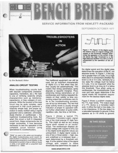
>> Download HP-Bench-Briefs-1977-09-10 documenatation <<
Text preview - extract from the document
                                               SERVICE INFORMATION FROM HEWLETT-PACKARD
                                                                                                 SEPTEMBER-OCTOBER 1977


                                                   TROUBLESHOOTER3
                                                                 IN
                                                               ACTION
                                                                                                  Flgun 1. TIL S t g d . In Un digital world,
                                                                                                  Unnktiwvalwofa [email protected]
                                                                                                  faepect to th.thfeshold voH.g# G9w-
                                                                                                  mines tho op#.tlon of the cimuk A 8lg-
                                                                                                  nal abornth. ht@ thre8hokl k I th.   n
                                                                                                  hlghMato nb whether it I 2.8V o 3.0V I
                                                                                                                             r      r       s
                                                                                                  unhparsrwtt to th. operation of Un cir-
                                                                                                  cuit


                                                                                                 the digital signal and this digital state
                                                                                                 determines the operation of the IC, not
                                                                                                 absolute leveis. In Figure 1, if the sig-
                                                                                                 nal is greater than 2.4 vdts, it Ts a high
                                                                                                 state and it is unimportant whether the
by Jim Bechtold, Editor                            The traditional equipment can still be        level is 2.8 or 3.0volts. Simitarly
                                                   used, but an important characteristic         low state the voltage must be below
                                                   of dgital IC's is that when they fail,        0.4 volts. It is not important what the
ANALOG CIRCUIT TESTING                                                                           absolute level is as long as it is below
                                                   they usually fail catastrophically. This
                                                   means that timing parameters rarely           this threshold. Thus when using an
When troubleshooting circuits built                                                              oscilloscope, the troubleshooter must
with discrete components (resistors,               degrade or become marginal. Thus,
                                                   observing timing parameters on an             over and over again determine if the
capacitors, transistors, etc.), the task                                                         signal meets the threshold require-
is one of verifying relatively simple              oscilloscope and making repeated de-
                                                   cisions on their validity (a time con-        ment for the desired digital state.
characteristics such as resistance,
capacitance, or bias voltages of com-              suming ordeal that contributes very lit-
                                                   tle to the troubleshooting process),          Figure 2 shows a problem created by
ponents. While the function of the total                                                         the TTL logic family. The output stage
circuit may be quite complex, each                 can all but be eliminated. The fact that
                                                   pulse activity exists is usually enough       of a TTL device is a transistor totem
component in that circuit performs a                                                             pole. In either the high or low state, it is
relatively simple task, and proper op-             indication of proper IC operation with-
                                                   out further observation of pulse width,       a low impedance. In the low state it is
eration is easily verified using a signal                                                        a saturated transistor to ground. lt thus
generator and a voltmeter, ohmmeter,               repetition rate, rise time o fall time.
                                                                              r
                                                                                                 appears as 5-10 ohms to ground.
diode checker, or oscilloscope - the
traditional troubleshoding tools. But              Figure 1 shows a typical TTL
                                                   (Transistor-Transistor-Logic) signal;
when this circuit is built in integrated           one of the most popular IC logic fam-
circuit form, these components are no              ily. This might as well be any analog
longer accessible. It now becomes
necessary to test the operation of the             signal when viewed on an oscillo-
                                                   scope. The oscilloscope displays ab-
complete circuit function using
specialized IC troubleshooters.                    solute voltage with respect to time, but
                                                   in the digital world absolute values are
                                                   unimportant. A digital signal exists in
"Node" as used in this article and throughout      one of two or three states -high, low,
the digital troubleshooting world means the        and undefined or in-between level -
pOini at which a cdlectbn of component termi-      each determined by a threshold volt-
rials end interconnections come together; or the
interseGtion or@nclh of two or more PC traces      age. It is the relative value of the signal
01 wires, o an e y e M wlth a component lead
            r                                      voltage with respect to these
W e f e d in It. -Ed&.                             thresholds that determines the state of
                                                          WWW.HPARCHIVE.COM
                                             job. However, in a production rmvi-         0 A short between an input or output
                         .
◦ Jabse Service Manual Search 2026 ◦ Jabse Pravopis ◦ onTap.bg ◦ Other service manual resources online : Fixya ◦ eServiceinfo