Service Manuals, User Guides, Schematic Diagrams or docs for : HP Publikacje an_380-1
<< Back | HomeMost service manuals and schematics are PDF files, so You will need Adobre Acrobat Reader to view : Acrobat Download Some of the files are DjVu format. Readers and resources available here : DjVu Resources
For the compressed files, most common are zip and rar. Please, extract files with Your favorite compression software ( WinZip, WinRAR ... ) before viewing. If a document has multiple parts, You should download all, before extracting.
Good luck. Repair on Your own risk. Make sure You know what You are doing.
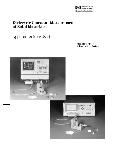
Image preview - the first page of the document
>> Download an_380-1 documenatation <<
Text preview - extract from the document
Dielectric Constant Measurement
of Solid Materials
Application Note 380-1
Using HP 16451B
Dielectric test fixture
1
Introduction (2) Additional Measurement Errors
can be Corrected.
To improve the quality of the dielectric solid mate-
rials such as polymer, electric insulator, PC board, Stray admittance and residual impedance of the
ceramic substrate etc., it is very important to eval- test fixture are the error sources in a dielectric
uate their electrical and physical characteristics, constant measurement. The HP 16451B can elimi-
such as molecular structure and density. The die- nate these additional error factors with the
lectric constant measurement is a very popular OPEN/SHORT error correction function of the
evaluation method. Using the HP 16451B Dielectric measurement instrument by using the furnished
Test Fixture with an HP LCR meter/Impedance OPEN/SHORT attachment. Edge capacitance is
Analyzer, accurate and easy dielectric constant and another error source (Figure 1). The HP 16451B
dissipation factor (tan ( ))1 measurements are can also eliminate the edge capacitance error by
possible. This application note explains the fea- using a guarded electrode (3-Terminal method).
tures and benefits of the HP 16451B and measure-
ment methods, and shows an example of
measuring a plate type dielectric materials.
Dielectric Constant Measurement Problems
The dielectric constant is calculated from the C-D
(Capacitance and Dissipation factor) measurement
results using an HP LCR meter/Impedance ana-
lyzer. However, there were many problems in the
realization of precise C-D measurement and easy
connections between the measurement instrument Edge Capacitance
and the test fixture. Thus dielectric constant meas-
urement was difficult.
Figure 1. Additional Error Due to Edge Capacitance
HP 16451B Main Features
and Benefits
(3) Interchangeable Electrodes
(1) The HP 16451B can be connected directly to
4-Terminal Pair measurement instruments. If a test fixture has only one type of electrode, it is
necessary to adjust the size of the Material Under
The 4-Terminal Pair measurement method adopted Test (MUT) or to form thin film electrodes on the
in recent impedance measurement instruments surface of the MUT.
offers accurate measurement over a wide measure-
ment range. However, there was no test fixture for Four types of electrodes are furnished with the HP
solid materials which could be connected directly 16451B so that the best electrode for the MUT can
to 4-Terminal Pair measurement instruments. The be selected. This eliminates the extra work and
HP 16451B can be connected directly to these makes it possible to evaluate the MUT while meet-
instruments to obtain accurate measurements. ing ASTM2 size requirements.
A description for each of the furnished electrodes
and their applicable measurement methods are giv-
en in Table 1.
2
Table 1. Electrode Selection Guide
Type of Electrode Electrode Dimensions MUT Dimensions
Electrode-A Diameter: Thickness:
(38 mm Guarded/ 40 mm ~ 56mm 10 mm
Guard Electrode) Applicable measurement method:
Contacting Electrode method
(Rigid Metal Electrode)
Non-contacting Electrode
method (Air Gap Method)
Electrode-B Diameter: Thickness:
(5 mm Guarded/ 10 mm ~ 56mm 10 mm
Guard Electrode) Applicable measurement method:
Contacting Electrode method
(Rigid Metal Electrode)
Non-contacting Electrode
method (Air Gap Method)
Electrode-C Diameter: 56mm Thickness:
(Guarded/Guard Electrode 10 mm
for Large Thin Film Diameter of guarded thin
Electrodes) film electrodes: 5 mm ~ 50mm (including the
thickness of thin
Inside diameter of guard thin film electrodes)
film electrodes: 52 mm
(greater than a diameter of guarded
thin film electrode)
Applicable measurement method:
Contacting Electrode method
(Thin Film Electrode)
Electrode-D Diameter: 20 mm ~ 56mm Thickness:
(Guarded/Guard Electrode 10 mm
for Small Thin Film Diameter of guarded thin
Electrodes) film electrodes: 5 mm ~ 14 mm (including the
thickness of thin
Inside diameter of guard thin film electrodes)
film electrodes: 16 mm
(greater than a diameter of guarded
thin film electrode)
Applicagle measurement method:
Contacting Electrode method
(Thin Film Electrode)
3
Applicable Measurement Methods The measurement error caused due to the air gap
between the MUT and the electrodes can be mini-
The HP 16451B offers three measurement meth- mized. Electrode-C or Electrode-D must be used.
ods. Each feature of these measurement methods (Figure 3).
is described below.
(1) Contacting Electrode Method (Rigid Metal Guarded
Electrode) Guarded thin electrode
film electrode
This method derives the dielectric constant using Guarded thin
film electrode Guard
the C-D measurement results (electrodes contact- electrode
ed directly to the MUT). This method requires only
MUT
one measurement to derive the dielectric constant
and does not need to use thin films applied to the
surface of the MUT. However, the surface must be
flat and have low compressibility to prevent an air Unguarded thin Unguarded
gap between the MUT and the electrodes which film electrode electrode
will cause measurement error. Electrode-A or Elec-
trode-B must be used. (Figure 2) Figure 3. Contacting Electrode Method
(Thin Film Electrode)
Guarded electrode The following equation is used to derive the dielec-
tric constant3 and dissipation factor is applicable
d to the above methods.
Guard electrode
MUT
ta
Parameters Needed:
Unguarded : Equivalent parallel capacitance of MUT [F]
electrode Cp
D : Dissipation factor of MUT (measured value)
ta : Average thickness of MUT [m]
A : Area of Guarded electrode [m2]
Figure 2. Contacting Electrode Method
(Rigid Metal Electrode) d : Diameter of Guarded electrode [m]
o
: Dielectric constant of free space = 8.854 x 10⁻¹² [F/m]
Equations:
(2) Contacting Electrode Method ta Cp
(Thin Film Electrode) r = A o
ta Cp
This method derives the dielectric constant from = 2
the C-D measurement results (electrodes contact a
thin film applied to the surface of the MUT). This
() d
2 o
Dt =D
measurement method also required only one meas-
Where,
urement to derive the dielectric constant. The thin
film electrode must be applied before the measure- r : Dielectric constant of MUT
ment, but this method can be used for MUTs whose Dt : Dissipation factor of MUT
surface is not flat or have low compressibility.
4
(3) Non-contacting Electrode Method (Air Gap
Method) (This method is not applicable to the
MUT with thin film electrodes).
Guarded
electrode
This method is used to derive the dielectric con-
Guard
stant by using the results of two C-D measurements electrode
ta ta
obtained with the MUT inserted between the elec-
trodes without it inserted between the electrodes.
This method requires two measurements. However,
MUT
accurate C-D measurements and dielectric constant
calculation are possible, because the air gap and Unguard
the compressibility of the MUT do not after the electrode
measurement result. Electrode-A or Electrode-B
must be used. (Figure 4).
The following equation is used to derive the dielec- Figure 4. Non-contacting Electrode Method
tric constant and dissipation factor applicable to (Air Gap Method)
this method.
Esquations:
1
r = Typical Measurement Example Using
1 ( 1
Cs1
Cs2 ) tg
ta the HP 16451B with the HP 4194A
Dt = D2 r ( D2 D1 ) ( tg
ta
1 ) The electrical and physical characteristics of mate-
rials are subject to change dependent on the meas-
Where, Dt2 < 1
< urement conditions and a materials frequency
r : Dielectric constant of MUT dependent characteristics is popularly used for
Dt : Dissipation factor of MUT material characterization. Frequency is one of the
popularly used factors to determine the character-
Parameters Needed: istics. So, it is very important to evaluate the die-
Cs1 : Capacitance wothout MUT inserted [F] lectric constant and dissipation factor of the
: Dissipation factor wothout MUT inserted
materials at the actual operating frequency.
D1
tg : Gap between Guarded/Guard electrode
Here is an example of evaluating the frequency
and Unguarded electrode [m] characteristics of the dielectric constant of a glass-
Cs2 : Capacitance with MUT inserted [F] epoxy laminate, one of the materials used for
: Dissipation factor with MUT inserted
Printed Circuit Boards (PCB), using the HP 16451B
D2
and the HP 4194A Impedance/Gain-phase Analyzer.
ta : Average thickness of MUT [m]
In this example. the dielectric constant and dissi-
pation factor (Figure 6) and the complex dielectric
constant4 (Figure 7) are automatically calculated
from the C-D measurement results and displayed.
This C-D measurement is made using the Non-con-
tacting method, and sweeping the frequency from
1kHz to 15MHz with the HP 4194A's internal pro-
gramming function, ASP (Auto Sequence Pro-
gram). The ASP program listing used for this
evaluation is shown in Figure 5.
5
6
Conclusion
The HP 16451B is the best test fixture to use with
an HP LCR meter/Impedance analyzer to simply
and accurately evaluate the dielectric constant
characteristics of solid materials.
Applicable measurement instruments:
HP 4192A, HP 4194A, HP 4274A, HP 4278A,
HP 4284A
1 Dissipation factor = Dt = tan( ) = Er"/Er'
2 ASTM - American Society for Testing and
Materials
3 In this application note, it means the Relative
Figure 6. Dielectric Constant and Dissipation Factor Dielectric Constant (Er).
of Glass-Epoxy Laminate
4 The dielectric constant modeled in the
complex form as follows considering the
"Dielectric after effect" phenomenon
Er* = Er' - jEr"
Er' = Er*cos ( ) = Er*cos [tan-1 (Dt)]
Er" = Er*sin ( ) = Er*sin [tan-1 (Dt)]
Figure 7. Complex Dielectric Constant of
Glass-Epoxy Laminate
7
For more information about Hewlett-
Packard test & measurement products,
applications, services, and for a
current sales office listing, visit
our web site, http://www.hp.com/go/tmdir.
You can also contact one of the following
centers and ask for a test and
measurement sales representative.
United States:
Hewlett-Packard Company
Test and Measurement Call Center
P.O. Box 4026
Englewood, CO 80155-4026
1 800 452 4844
Canada:
Hewlett-Packard Canada Ltd.
5150 Spectrum Way
Mississauga, Ontario
L4W 5G1
(905) 206 4725
Europe:
Hewlett-Packard
European Marketing Centre
P.O. Box 999
1180 AZ Amstelveen
The Netherlands
(31 20) 547 9900
Japan:
Hewlett-Packard Japan Ltd.
Measurement Assistance Center
9-1, Takakura-Cho, Hachioji-Shi,
Tokyo 192-8510, Japan
Tel: (81) 426 56 7832
Fax: (81) 426 56 7840
Latin America:
Hewlett-Packard
Latin American Region Headquarters
5200 Blue Lagoon Drive
9th Floor
Miami, Florida 33126
U.S.A.
Tel: (305) 267-4245
(305) 267-4220
Fax: (305) 267-4288
Australia/New Zealand:
Hewlett-Packard Australia Ltd.
31-41 Joseph Street
Blackburn, Victoria 3130
Australia
Tel: 1800 629 485 (Australia)
0800 738 378 (New Zealand)
Fax: (61 3) 9210 5489
Asia Pacific:
Hewlett-Packard Asia Pacific Ltd.
17-21/F Shell Tower, Times Square,
1 Matheson Street, Causeway Bay,
Hong Kong
Tel: (852) 2599 7777
Fax: (852) 2506 9285
Data subject to change
Copyright ◦ Jabse Service Manual Search 2026 ◦ Jabse Pravopis ◦ onTap.bg ◦ Other service manual resources online : Fixya ◦ eServiceinfo