Service Manuals, User Guides, Schematic Diagrams or docs for : HP terminal 264x 13255-91112_Display_Controller_Module_Sep77
<< Back | HomeMost service manuals and schematics are PDF files, so You will need Adobre Acrobat Reader to view : Acrobat Download Some of the files are DjVu format. Readers and resources available here : DjVu Resources
For the compressed files, most common are zip and rar. Please, extract files with Your favorite compression software ( WinZip, WinRAR ... ) before viewing. If a document has multiple parts, You should download all, before extracting.
Good luck. Repair on Your own risk. Make sure You know what You are doing.
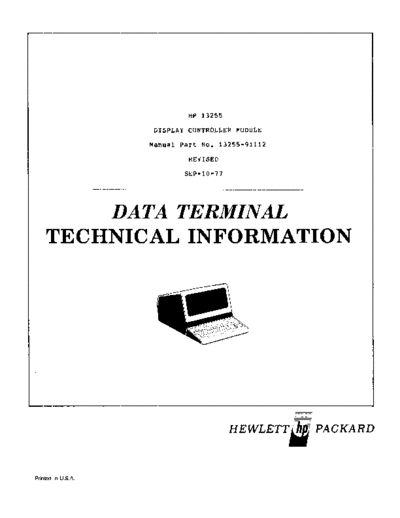
Image preview - the first page of the document
>> Download 13255-91112_Display_Controller_Module_Sep77 documenatation <<
Text preview - extract from the document
                             HP 13255

                    DISPLAi CONTROLLER   MODUL~


                    Manual Part No. 13255-91112

                             REv'ISED

                            SEP-IO-77


        DATA TERMINAL
    TECHNICAL INFORMATION


                                        HEWLETTi:j PACKARD


Printed in U.S.A.
13255                                                             13255-91112/02
Display Controller Module                                         Rev SEP-10-77


1.0      INTRODUCTION.

1.1      GENERAL   DESCkIPTIO~.


         The Display Controller ~odule is a high speed, special purpose 110
         device. Its function is to provide drive signals to the CRT monitor,
         initiate data transfers from the terminal memorY, and convert ASCII
         characters into a video signal.
         The full screen capaoility Of the display is 24 rows of 80 characters
         each. The minimum system can display 64 characters with one display
         feature--inverse video fields. An additional 64-cha~acter ROM may be
         added to the baSic system for 128-character operation.
        The Display Memory Access PCA (OMA) is that portion of the Display
        Controller Module which reads characters from the memory, buffers them
        in BO-character shift registers, and sends them to the Display Timing
        and Display Control PCA's. The operation of the DMA is controlled by
        the Display Timing and Display Control PCA's which initiate the trans-
        fer of ~ows of characters. It should be noted that there are two
        possible Display Control PCAs. Unless otherwise noted, reference to
        the Display Control PCA will apply to both assemblies.

1.2      PACKAGING.
        The Display Controller Module consists Of three PCA's, the Display
        Control, Display Timing, and tne Display Memory Access PCA's. The DMA
        is adjacent to the Display Timing and Display Control PCA's and all
        three boards are connected together with tne Top Plane Connector Assem-
        bly. The connection to the CRT monitor is made with the Sweep Cable
        Assembly from the CRT monitor to the Display Timing peA.

1.3     CHARACTER FONT.
        The basic character cell is a 9-dot by 1S-scan line rectangle. ~ithin
        this cell is the 7 x 9 Character surrounded by one dot on either side
        for horizontal spacing, four scan lines below for lower case cnaracter
        descenaers, and one scan line above and oelow tor row-to-row spacinq.
        The appearance ot the characters is ennanced by means of a half-shift
        capability which generates smoother angles and curves by utilizing
        extra bits in the character ROMS. Eacn character scan line segment is
        stored in ROM as an 8-bit word. Seven of the bits (bITI-BIT7) corres-
        pond to the aot positions Dl-07 within the cnaracter cell. The eighth
        bit (BITO) controls whether the dots will occur durinq the normal 10t
        times or will be delayed by one-half dot time, corresponding to a shift
        to the right by nalf a dot position on the screen. This increases the
        effective character resolution to 13 x 9; seven u~shifted dot positions
        and six interstitial positions.
                                           HP 13255
                                  DISPLAY CONTROLLER   MODUL~


                                 Manual Part No. 13255-91112
                                           REVISED
                                          SEP-I0-77


                               -------------------------------------------------------
                                           NOTICE
           The information contained in this document is subject to   chang~
           without notice.
           HEWLETT-PACKARD MAKES NU WARRANTY OF ANY KIND WITH REGA~O TO THIS
           MATERIAL, INCLUDING, dUT NOT LIMITED TO THE IMPLIED WARkANTIFS OF
           MERCHANTABILITY AND FITNESS FOR A PARTICULAk PURPOS~. HeWlett-Packard
           shall not be liable for errors contained herein or for incidental or
           consequential damages in connection with the furnishing, performance,
           or use of this material.
           This document contains proprietary information which is protected by
           copyright. All rights are reserved. No part of this document may be
           Photocopied or reproduced without the prior written consent of Hewlett-
           Packard Company.

----- ..   -----~--~-----~---~---------------------------------~------------~--------
                        Copyright c 1976 by HEWLETT-PACKAR0 COMPANY


              NOTE:   This document is part of the 264XX DATA T~RMINAL product
                      series Technical Information PaCKage (HP 13255).
13255                                                             13255-91112/02
Display Controller MOdule                                         Rev SEP-IO-77


1.0      INTRODUCTION.

1.1      GENERAL   DESCkIPTIO~.


         The Display Controller ~odule is a high speed, special purpose 110
         device. Its function is to provide drive signals to the CRT monitor,
         initiate data transfers from the terminal memorY, and convert ASCII
         characters into a video signal.
         The full screen capaoility of the display is 24 rows of 80 characters
         each. The minimum system can display 64 characters with one display
         feature--inverse video fields. An additional 64-cha~acter ROM may be
         added to the basic sys~eru for 128-character operation.
        The Display Memory Access PCA (OMA) is that portion of the Display
        Controller Module which reads characters from the memory, buffers tnem
        in 80-character shift registers, and sends them to the Display Timing
        and Display Control PCA's. The operation of the DMA is controlled by
        the Display Timing and Display Control PCA's which initiate the trans-
        fer of rows of characters. It should be noted that there are two
        possible Display Control PCAs. Unless otherwise noted, reference to
        the Display Control PCA will apply to both assemblies.

1.2      PACKAGING.
        The Display Controller Module consists Of three peA's, tne Display
        Control, Display Timing, and tne Display Memory Access PCA's. The DMA
        is adjacent to the Display Timing and Display Control PCA's and all
        three boards are connected together with tne Top Plane Connector Assem-
        bly. The connection to the CRT monitor is made with the sweep Cable
        Assembly from the CRT monitor to the Display Timing PCA.

1.3     CHARACTER FONT.
        The basic character cell is a 9-dot by IS-scan line rectangle. ~ithin
        this cell is the 7 x 9 Character surrounded by one dot on either side
        for horizontal spacing, tour scan lines below for lower case cnaracter
        descenaers, and one scan line above and oelow tor row-to-row spacinq.
        The appearance ot the characters is ennanced by means of a half-shift
        capability wnich generates smootner angles and curves by utilizing
        extra bits in the character ROMS. Edcn character scan line segment is
        stored in ROM as an ij-bit word. Seven of the bits (~ITl-8IT7) corres-
        pond to the aot positions D1-07 within the cnaracter cell. The eighth
        bit (BITO) controls whether the dots will occur durinq the normal 10t
        times or will be delayed by one-half dot time, corresponainq to a shift
        to the right by naIf a dot position on the screen. This increases the
        effective character resolutlon to 13 x 9; seven u~shifted dot positions
        and six interstitial positions.
13255                                                                       13255-91112/03
Display Controller Module                                                   Rev SEP-I0-77


1.4        DISPLA~   TIMING AND CONTROL-DMA INTERFACE.
           The two communication paths between the DMA and the Display Timinq and
           Control PCA's consist of the control siqnals between tne PCA's and the
           returned data to be displayed.
           In practice, a pair of odd/even character shift registers store one row
           each of chdracters and their enhancement fields. While a row is being
           scanned and aisplayed from one odd/even character shift register, the
           next row is being loaded into the other odd/even character shift reqis-
           ter by the DMA. The oad/even character shift registers are togqled at
           the end of each row of characters.

1.5        DISPLAY CONTROLLEP-PROCESSOR INTERFACE.
           The Display Controller Module is the recipient of the cursor X and Y
           position on the screen. When the cursor is to be positioned to a new
           location, the processor outputs either a new cursor X or Y position.
           These positions are strooed into registers and are used to generate
           the visible cursor. No data or control paths exist from the display
           b~ck to the processor.


           In addition, the Display Controller MOdule receives two commands, one
           which turns the DMA on or oft, and the other wnich turns the display
           on and off. '

2.0        OPERATING PARAMETEHS.
           A summary of operatinq parameters for the DisPlay Controller Module
           is contained in tables 1.0 through 6.2.
                             Table 1.0     Pnysical Parameters
============:====================================================================
       Part                                              Size (L x W x D)      I    Weight
      Number    I           Nomenclature            I     +/-0.100 Inches      I   (Pounds)
 =============1==============================1=======================1=========
  02640-60112 1 Display Control peA          I 12.9 x 4.0 x 0.5          0.44
  02640-60152 I Display Control peA                 I    12.9 x 4.0 x 0.5           0.44
  02640-60009 I Display Memory Access peA                12.5 x 4.0 x 0.5           0.38
                I
  02640-60088 I Display Timing PCA                       12.5 x 4.0 x 0.6           0.31
              I
  02640-60012 I Top Plane Connector Assembly                     N/A                  N/A
 ===========:===================================================================
                     Number of Backplane Slots Required:     3

================================================================================
13255                                                                              132S5-91112/04
Display Controller Module                                                          Rev SElJ-10-77


                   Table 2.0       Reliability ana Enviromental Information


----------~------~------~---~-~---~-~-----~--~------~-----~---------------------
-------~~--------------~---~---~---~--~~----~----------------------~------------


   t;nvironmental:            ( X ) HP Class li       (       ) Other:

   Restrictions:         Type tested at product level


 ==============================================================================
                       Failure Rate:      2.527   (percent per 1000 hours)

----------------------~-~-------~-----------------------~-~---------------------
----------~------------------------------~---------~-- --------------------------


                 Table 3.0       Power Supply and Clock Requirements - Measured
                                 (At +1-5% Unless Otherwise Spec1fied)

--------~---------------------~~-~--~-~~~----~----~-------~--------------~------
---------~--~--------~----~----~-~-~~---~~----------~--------------------~------

   +5 Volt Supply            +12 Volt Supply        -12 Volt Supply           -42 Volt Supply

        fa   1600 mA              ~ 68  rnA               @   27   rnA             @    rnA
                             (02640-60152 only)
  (MODULE TOTAL)                 NOT APPLICABLE      CDMA peA ONLY)            NOT APPLICABLE
 ====================================== =======================================
                  115 volts ac                                      220 volts ac

                             A                                                 A

                 NOT APPLICABLE                                    NOT   APPLICAHLE
 ---------------------------------------~----~------------------~-~--------~---
 ----~----~----------~----~~---~~------------~----~---- ------------------------

             ClOCK frequency:       21.060 MHz (DISPLAY TIMING AND CONTROL PCA'S)
                                     4.915 MHZ CDMA peA)

================================================================================
13255                                                                 13255-91112/05
Display Controller Module                                             Rev SEP-10-J7


                            Taole 4.0   Jumper Definitions

        ..
-----.------~----~-------~--------~---~-~~-~~----~--~--~-~-~---------------------
--~-- -~---~---------~-----------~----~----~---~~-~---------------~-~-----------
                                                 Function
       peA
   Designation      I---------------
◦ Jabse Service Manual Search 2026 ◦ Jabse Pravopis ◦ onTap.bg ◦ Other service manual resources online : Fixya ◦ eServiceinfo