Service Manuals, User Guides, Schematic Diagrams or docs for : Harman Kardon AVR AVR-325 AVR-325
<< Back | HomeMost service manuals and schematics are PDF files, so You will need Adobre Acrobat Reader to view : Acrobat Download Some of the files are DjVu format. Readers and resources available here : DjVu Resources
For the compressed files, most common are zip and rar. Please, extract files with Your favorite compression software ( WinZip, WinRAR ... ) before viewing. If a document has multiple parts, You should download all, before extracting.
Good luck. Repair on Your own risk. Make sure You know what You are doing.
Image preview - the first page of the document
>> Download AVR-325 documenatation <<
Text preview - extract from the document
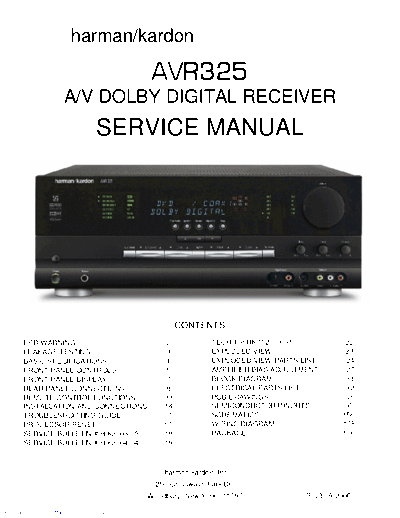
                            harman/kardon

                                                            AVR325
                         A/V DOLBY DIGITAL RECEIVER
                                      SERVICE MANUAL


                                                                  CONTENTS
        ESD WARNING......................................2                  TECH TIP HKTT2003-01......................22
        LEAKAGE TESTING.................................3                   EXPLODED VIEW...............................23
        BASIC SPECIFICATIONS.........................4                      EXPLODED VIEW PARTS LIST.............24
        FRONT PANEL CONTROLS.....................5                          AMPLIFIER BIAS ADJUSTMENT............27
        FRONT PANEL DISPLAY.........................7                       BLOCK DIAGRAM...............................31
        REAR PANEL CONNECTIONS..................8                           ELECTRICAL PARTS LIST....................32
        REMOTE CONTROL FUNCTIONS.............11                             PCB DRAWINGS................................83
        INSTALLATION AND CONNECTIONS........14                              SEMICONDUCTOR PINOUTS...............95
        TROUBLESHOOTING GUIDE.................... 17                        SCHEMATICS...................................156
        PROCESSOR RESET.............................17                      WIRING DIAGRAM................... ..........175
        SERVICE BULLETIN # H/K2003-05...........18                          PACKAGE........................................176
        SERVICE BULLETIN # H/K2004-04...........19


                                                               harman/kardon, Inc.
                                                             250 Crossways Park Dr.
                                                           Woodbury, New York 11797                         Rev3 9/2006

Downloaded from www.Manualslib.com manuals search engine
               AVR325                                                                                                                           harman/kardon


                 Some semiconductor (solid state) devices can be damaged easily by static electricity. Such components commonly are called

                 Electrostatically Sensitive (ES) Devices. Examples of typical ES devices are integrated circuits and some field effect transistors and

                 semiconductor "chip" components.

                 The following techniques should be used to help reduce the incidence of component damage caused by static electricity.

                 1. Immediately before handling any semiconductor component or semiconductor-equipped assembly, drain off any electrostatic charge on

                   your body by touching a known earth ground. Alternatively, obtain and wear a commercially available discharging wrist strap device,

                   which should be removed for potential shock reasons prior to applying power to the unit under test.

                 2. After removing an electrical assembly equipped with ES devices, place the assembly on a conductive surface such as aluminum foil, to

                   prevent electrostatic charge build-up or exposure of the assembly.

                 3. Use only a grounded-tip soldering iron to solder or unsolder ES devices.

                 4. Use only an anti-static solder removal device. Some solder removal devices not classified as "anti-static" can generate electrical charges

                   sufficient to damage ES devices.

                 5. Do not use freon-propelled chemicals. These can generate electrical change sufficient to damage ES devices.

                 6. Do not remove a replacement ES device from its protective package until immediately before you are ready to install it. (Most replacement

                   ES devices are packaged with leads electrically shorted together by conductive foam, aluminum foil or comparable conductive material.)

                 7. Immediately before removing the protective material from the leads of a replacement ES device, touch the protective material to the

                   chassis or circuit assembly into which the device will be installed.

                  CAUTION : Be sure no power is applied to the chassis or circuit, and observe all other safety precautions.

                 8. Minimize bodily motions when handling unpackaged replacement ES devices. (Otherwise harmless motion such as the brushing together

                   or your clothes fabric or the lifting of your foot from a carpeted floor can generate static electricity sufficient to damage an ES devices.


                 Each precaution in this manual should be followed during servicing.

                 Components identified with the IEC symbol        in the parts list are special significance to safety. When replacing a component identified with

                     , use only the replacement parts designated, or parts with the same ratings or resistance, wattage, or voltage that are designated in the

                 parts list in this manual. Leakage-current or resistance measurements must be made to determine that exposed parts are acceptably

                 insulated from the supply circuit before retuming the product to the customer.


Downloaded from www.Manualslib.com manuals search engine
             AVR325                                                                                                                      harman/kardon


                 Before returning the unit to the user, perform the following safety checks :


                 1. Inspect all lead dress to make certain that

                   leads are not pinched or that hardware is not

                   lodged between the chassis and other metal

                   parts in the unit.

                 2. Be sure that any protective devices such as

                   nonmetallic control knobs, insulating fish-

                   papers, cabinet backs, adjustment and

                   compartment covers or shields, isolation

                   resistor-capacity networks, mechanical

                   insulators, etc. Which were removed for the

                   servicing are properly re-installed.

                 3. Be sure that no shock hazard exists ; check for leakage

                   current using Simpson Model 229 Leakage Tester, standard

                   equipment item No. 21641, RCA Model WT540A or use

                   alternate method as follows : Plug the power cord directly

                   Into a 120 volt AC receptacle (do not use an Isolation

                   Transformer for this test). Using two clip leads, connect a

                   1500 ohms, 10watt Resistor paralleled by a 0.15uF capacitor, in series with all exposed metal cabinet parts and a known earth ground, such

                   as a water pipe or conduit. Use a VTVM or VOM with 1000 ohms per volt, or higher sensitivity to measure the AC voltage drop across the

                   resistor. (See diagram) Move the resistor connection to each exposed metal part having a return path to the chassis (antenna, metal,

                   cabinet, screw heads, knobs and control shafts, escutcheon, etc.) and measure the AC voltage drop across the resistor. (This test should be

                   performed with the 0.35 volt RMS or more is excessive and indicates a potential shock hazard which must be corrected before returning the

                   unit to the owner.


Downloaded from www.Manualslib.com manuals search engine
          AVR325                                                                                                                                           harman/kardon

                                                                 AVR 325 TECHNICAL SPECIFICATIONS

        Audio Section                                               AM Tuner Section
        Stereo Mode                                                       Frequency Range                                 325
◦ Jabse Service Manual Search 2026 ◦ Jabse Pravopis ◦ onTap.bg ◦ Other service manual resources online : Fixya ◦ eServiceinfo